Cinemascope Information for the Theater
Published in October 1954 by Twentieth Century-Fox Film Corporation - Second Edition Third Revision
|
A year has now elapsed since CinemaScope was first introduced into the theatre. The fact that stands out most clearly from this past experience is that the basic engineering decisions behind CinemaScope have been supported and confirmed—nowhere has there been any evidence indicating that the film specifications, optical concepts, or stereophonic sound engineering designs should be changed f the standards chosen. As time goes on, technological improvements will inevitably be made; a firm foundation has been provided for these improvements. For example, factual evidence is at hand that the life of the magnetic sound heads shortly to reach the market will be markedly longer than that of the present clusters; even though the present heads, if properly adjusted, in the theatre, will reproduce satisfactorily many millions of feet of film. The new sprocket holes—where the sprockets have been installed as specified herein—have yielded longer film life than the formerly used positive perforations; reliability of magnetic tracks has been established, and the cost of application has decreased markedly. This booklet has therefore been completely revised in an effort to bring it up to date, in the light of this experience, and particularly to help the theatre owner, exhibitor, projectionist, and service engineer to maintain his theatre equipment in such manner as to profit fully from the potentials of CinemaScope. The information contained herein was compiled by the Research and Development Division of the Twentieth Century-For Film Corporation, under the direction of Mr. E. I. Sponable, with the collaboration of Messrs.H. E. Bragg, L. D. Grignon, and F. D. Leslie. October 1954 PRINTED IN U.S.A. INDEX 3.20 Aperture (Standard 4-track) 5.10 Loudspeaker Systems—Screen 5.20 Loudspeaker Systems—Surround 6.0 OPERATION AND FILM HANDLING 7.0 OUTDOOR (DRIVE-IN) THEATRES APPENDIX 1.0 CINEMASCOPE—SINGLE MAGNETIC SOUND 2.0 CINEMASCOPE—PHOTOGRAPHIC TRACKS (OPTICAL SOUND) LIST OF ILLUSTRATIONS Fig. 1 Film and Sprocket Dimension Layout Fig. 4 Typical Picture and Aperture Shapes Fig. 6 Demagnetizing Intermittent Sprocket Assembly Fig. 7 Demagnetizing Upper Feed Sprocket Fig. 8 Demagnetizing Keeper Roll Fig. 9 Demagnetizing Picture Gate Rails after Disassembly Fig. 10 Demagnetizing Picture Gate Guide Roller Fig. 11 Demagnetizing Back Picture Gate Casting after Removal of Rails—Step 1 Fig. 12 Demagnetizing Back Picture Gate Casting after Removal of Rails—Step 2 Fig. 13 Demagnetizing Intermittent Sprocket Shoes Fig. 14 Demagnetizing Picture Gate Pressure Pad Shoes Fig. 15 Demagnetizing Optical Sound head Scanning Drum Fig. 16 Demagnetizing Magnetic Sound Pickup Head Fig. 17 Demagnetizing Cutting Bar of Splicing Block Fig. 19 Testing for Magnetization with Compass Fig. 20 Testing for Magnetization with Suspended Pin Fig. 21 Outline of CinemaScope Attachment 41-77-04 Fig. 22 Outline of CinemaScope Attachment 41-77-02 Fig. 23 Photograph of Typical Sound Head and CinemaScope Attachment on Projector Fig. 24 Typical Distribution of Miracle Mirror Flat Screens Fig. 25 Typical Distribution of Miracle Mirror Tilted Screen Fig. 26A-26B Sound Reproducing Frequency Characteristics Fig. 27 CinemaScope Release Film Leader Fig. 28 Projection Aperture—(Optical Prints) Table I Projection Table—Picture Size—Full CinemaScope Aperture—(40’—200’ Projection Distance) Table II Screen Widths and Depth of Curve for Curved Screens Table III Projection Table—Picture Size—Full CinemaScope Aperture—(200’ Projection Distance) Table IV Projection Table—Picture Size—Optical Print Aperture CINEMASCOPE IN THE THEATRE EQUIPMENT INFORMATION, INSTALLATION PROCEDURES MAINTENANCE AND OPERATING PRACTICES This booklet has been prepared to provide the distributor, exhibitor and operating personnel with some basic understanding of CinemaScope, to indicate equipment changes, to describe installation procedures, apparatus adjustment, differences in handling practice, and precautions which should be observed, as well as certain operating features. These notes have been care fully brought up to date on the basis of all present knowledge with the idea of facilitating an orderly preparation and smooth operation for a showmanlike presentation of CinemaScope product. The Drive-In theatre is a unique operation and a section (7.0) is devoted specifically to applicable material, It is desirable, however, that the outdoor theatre exhibitor peruse all of the in formation in this handbook so that he may have an understanding of CinemaScope and then reference can be made to the Drive-In theatre section for the details of particular interest. Since prints of CinemaScope pictures are being released with !optical photographic and magnetic single track sound recording, material pertinent to these kinds of operations are included in this handbook as an appendix. CinemaScope is a completely engineered system for the practical presentation of wide screen pictures combined with true stereo phonic sound. Stereophonic sound is a method of recording and reproduction which, in effect, recreates the original sound performance on the screen as though the performance were actually there. Stereophonic sound requires the use of a multiplicity of microphones with separate and individual recording channels and records for each; the reproducing system requires the same number of separate channels and loudspeakers. Stereophonic sound includes, as one distinct feature, the directionality, or localization, of sound sources corresponding to the visual location of the source on the screen hut has additional definite and desirable features not otherwise obtainable. Directional or pseudo-stereophonic sound is recorded with a single recording channel, as have all past motion pictures which have had world wide release, and employs a multiplicity of reproducing channels and loudspeakers. it has only the feature of directionality and whatever effects of perspective might be synthesized. CinemaScope is so designed as to provide the greatest approach to realism in motion picture story telling which has yet been achieved. This realism is possible because the CinemaScope scheme permits using lenses during the photography which gives the most natural perspective; the angles of view in the presentation of CinemaScope approach that to which we are accustomed in life and the effect of stereophonic sound is to assist in bringing the performance to the stage or area before the audience. All of the factors of depth perception except stereoscopic vision are used but two inter-locking projectors and films are not required. CinemaScope is not a so-called 3-dimension system. CinemaScope is not a temporary expedient of "blow-up" or wide screen presentation such as has been used to some extent on product which has not been produced with this in mind, nor is the stereophonic sound associated with Cinema any engineering compromise. All films produced in CinemaScope have been specifically staged and photographed with this medium in mind. The screen shape (not just the size) has been chosen as the closest practical approach to peripheral vision as it seems possible to do today, without putting a considerably greater cost burden on the exhibitor than is required for CinemaScope. It can be demonstrated that CinemaScope gives an excellent presentation for nearly all the seats in a theatre. Further, screen shape is sufficiently different from past product so that it is noticeable to the audience rather than merely going part way in this regard. To reiterate, the effect on the audience in any particular theatre is not alone a matter of size and aspect ratio. What Cinema- Scope tries to do is give a better approach to realism, where the director desires it; to do this, the audience must see a scene through the eye of the camera just as though he were standing where the camera is located. Obviously, this can never be done one hundred per cent for all seats in the theatre, but the best results occur when the picture goes from side wall to side wall and appears to be the end of the theatre itself. To satisfy yourself that the CinemaScope proportions are well chosen, look straight ahead and then notice how much you see with reasonable clarity on each side and above and below center, —you will come out with a mental picture that is about the shape of CinemaScope (even though people differ somewhat, of course). You can see roughly 2V times as much sideways as vertically, unless you deliberately roll your eyes around to their extreme position which is, of course, tiring. Thus you see that the aspect ratio of CinemaScope is a result of the way we see, not a figure simply chosen out of thin air. The CinemaScope picture has sometimes been referred to as a "ribbon of picture’’; this is a false statement because it strongly implies that the picture has very little height and great width. The height of any picture in the usual theatre is determined by the sight lines of the house and it is emphasized that every ef fort should be made to continue at least the same picture height in the theatre as is used for any other product. No picture system or any other aspect ratio can put any greater picture height in the theatre than is dictated by the sight lines. Once the height is fixed the width for CinemaScope is determined by the aspect ratio, i.e. by multiplying the height by 2.55. Under the stated circumstances the resulting picture will be roughly twice as wide as the old picture for the same height. If a situation exists in a particular theatre which positively limits the picture width, then the height is determined by dividing the maximum width by 2.55. In dealing with a number of small theatres it has been found that, with thought and engineering ingenuity, it was possible to install a screen of considerable width and the resulting picture height for CinemaScope was essentially the same as the prevailing height in the theatre. Actually, if the existing projection lens is used with CinemaScope the resulting screen image will have greater height than the conventional picture because the 35mm. film is being used to greater advantage by employing a frame with 19% greater height. Properly handled, this added height of the picture frame in the camera is advantageous in reducing the grain, since it means that, for the same height picture, less magnification is required in the theatre. The story telling must be handled differently and approaches that of legitimate stage technique but still maintains the unique feature of motion pictures where scenes can be rapidly changed at will. The closeup is used less frequently but is as important as ever and the intimate scene is not ruled out. In photographing the picture a special optical system, technically described as "anamorphic’’, is used instead of the conventional camera lens. The anamorphic unit "looks" at a wider picture than the conventional lens but does not in the least way affect the height, the result being as though the picture were photographed in a horizontal direction with a very wide angle lens but with an ordinary lens in the vertical direction. Observation of the image on the negative, or the print made there from, will show that the image is squeezed in the horizontal direction. All objects seem to be thinner than they should be. By adding to the projector an anamorphic optical attachment (which has precisely the opposite effect to the taking system) in combination with the existing projector lens, the image is restored optically to its correct proportions and the picture on the theatre screen is a true reproduction, in all of its proportions, of the original scene. In this way it is possible to get a very wide picture on a standard piece of 35mm. film and use all of the avail able area on the film. In order to provide as large an image on the film as possible, to reduce the magnification required in the theatre, to maintain resolution, to minimize grain and to provide space for the sound tracks, it has been found entirely practical and good engineering to reduce the size of the sprocket holes on the film. The reader can easily observe that the sprocket holes have less width than the present standard film and that they are located near the outer extremes of the existing sprocket holes. (See Fig. 1) Since a larger picture results from the CinemaScope system, the screen brightness suffers unless the screen is improved or the projector illumination is increased. A special screen has been developed which, compared to the ordinary diffuse flat screen formerly employed in the theatre, increases the picture brightness to make up for the loss in brightness due to picture size. Other standard types of screens have been improved, and with proper illumination, are acceptable in appropriate size theatres. Stereophonic sound, properly recorded and projected, adds a great deal of realism to the picture presentation. It not only has features of direction—that is,
sounds appear to come from where the source is seen on the screen—but in addition to this the perspective, the acoustic character of the space around the performers, and the overall sound quality and naturalness are greatly improved. Provision has also been made in the CinemaScope system for the use of auditorium, or surround, speakers for special effects when such effects add to the value of the picture entertainment. Since a whole new sound system is involved in this case, from producing through exhibition, advantage has been taken of this opportunity to introduce magnetic type sound recordings by which means it is possible to provide in the theatre better technical performance than can be had with any known optical systems. CinemaScope stereophonic sound is definitely not to be compared with systems possessing only ‘directional" characteristics, some of which have been widely advertised as stereophonic.
Because of the change in the film standards, the amount of space used by the image, the kind of image and stereophonic sound certain additions to and modification of the booth equipment must be made. These are as follows: The sprocket hole size on the film and their relative spacing have been changed. The film dimensions are shown in Fig. 2. This requires that all of the sprockets and perhaps some of the keepers and pad rollers must be changed. By inspection of Fig. 1 it will be seen that the designs have been produced in such a manner that the new sprockets will handle all existing and past product except, possibly, badly shrunken nitrate film. It is obvious that with the new sprockets it is not necessary that the projectionist change these to project any other product which presently exists, but it is imperative that CinemaScope product is not run until such sprocket change has been effected.
In view of the better technical art available today, all of the tolerances for shrinkage and manufacture have been minimized and it is important that the intermittent sprocket be accurately lined up with the edge guiding element in the projector so that the sprocket tooth nearest the guided edge will engage the perforation in the center of the hole. The adjustment of pad and keeper roller clearances should be carefully made according to manufacturer’s specifications. All new parts, as well as all parts of the reproducers, should preferably be demagnetized after rather than before installation to eliminate residual fields which result from manufacture or handling. Whenever mechanical work is done on the magnetic re producing head, these parts should be demagnetized. (See Sec.3.40) As at present, a take-up adjustment that is too tight will cause nicking on the back edge of the perforation and therefore this should be watched. Large hub reels and slow starting motors minimize this possibility. (Also see Section 6.0.) The question as to film durability is invariably asked. Comparative life tests, under controlled and reproducible conditions, have been made with existing standard films and with CinemaScope. Every test has shown CinemaScope film to be at least the equal of the older types and if the recommended CinemaScope sprock ets are used, the life of CinemaScope film is three to four times as great as can be expected from former standard practice. The considerable improvement in wear derives principally from the use of intermittent sprockets having a base pitch diameter of 0.953 inch rather than the formerly recommended 0.943 inch. Although many tests have always confirmed the value of over- pitched sprockets, their adoption has been slow indeed. A change in standards, such as CinemaScope has made, supplied the opportunity to make good use of the knowledge at hand. 3.20 Aperture (Standard CinemaScope 4 Track Magnetic Sound Prints) The size and placement of the CinemaScope image on the film is different from the present standard size and position and hence a new aperture plate is required (See Fig. 3). The standard size of this aperture plate is 0.912 by 0.715 inches and a plate with an opening of these dimensions may be used if the projection angle is low so that the small amount of picture keystoning that occurs might be taken care of by the screen masking. In the case of steep projection angles, it will be necessary to obtain an aperture plate with somewhat smaller dimensions of the opening
to permit shaping of the aperture to correct the larger amounts of picture keystone. The method of correcting for horizontal and vertical keystone is the same as now practiced whereby the top edge of the aperture is made shorter than the bottom and the sides sloped to meet the lower edge. In addition it may be found desirable also to correct for the projector offset from the screen center line, and in this case, one side or the other will be longer. With a curved screen as used for CinemaScope, the bottom, and often the top, of the screen picture will be curved. Should this curvature be considerable it is also desirable to shape the aperture top and bottom to obtain picture edges parallel to the masking. Exaggerated drawings of typical plates are shown in Fig. 4. Because of the large magnification in the horizontal direction filing of the plate for correction must be very carefully done with the finest grade of flat files with safety edges. For example, a picture 50 feet wide is about 600 times the film image size, therefore, ten thousandths of an ihch in the horizontal direction on the plate would make a six-inch change in picture. The CinemaScope aperture of .912 x .715 inches makes more efficient use of the light from the arc lamp than any other aperture sizes used in theatres today. For instance, compared to the 1.37 to I standard ratio it passes approximately 22% more light. The apertures of aspect ratios of 1.66 to 1, 1.75 to 1, 1.85 to 1 and 2.00 to 1 using the standard width of .825 inches pass even less light than the standard aperture of 1.37 to 1 ratio (.825 x .600 inches). In some cases, due to the larger aperture, there may be obstruc tions to the light path in the projector. These will be observed as loss of light or fuzzy edged shadows around the picture periphery. In some projectors the obstruction can be the light baffles or the light beam openings in the castings or housings. Correction may require minor mechanical work to clear these openings. With the CinemaScope attachment on a long focal length lens it may be found necessary to extend the front shutter and/or shutter guard on some projector models; if it is more convenient, a single rear shutter could be used as has been done in the past. The magnetic sound heads supplied by all manufacturers are installed between the upper magazine and the top of the projector casting. Because of this arrangement, the picture precedes the sound on the composite film and a standard displacement of 28 frames has been adopted. Therefore, adaptor plates must be used or the film path length, between the picture aperture and sound pickup head, adjusted to meet this offset on the various models of projectors. It may also be necessary to change the upper magazine type or use an adaptor plate to fit the magazine to the sound head. The specific equipment situation should be investigated at the time of ordering sound heads and other parts to avoid later delays and troubles. In some cases, as with old equipment, the installation may require some mechanical work on the projector to permit the installation of the sound head.
3.40 Demagntization (Degaussing) Magnetic recording is accomplished by subjecting a magnetizable soundtrack to a constantly varying pattern of a magnetic field which corresponds to the original sounds. This process sets up in the magnetic tracks a pattern of microscopically small magnets whose influence is used during reproduction to generate electric currents to recreate the original sound. Obviously then, if these magnetic tracks are somehow exposed to magnetic fields other than that produced in the sound printing or recording process, extraneous sounds may, under certain conditions, be effectively recorded on the track. Further, if a magnetic recording is subjected to a sufficiently strong magnetic field, partial or complete erasure of the magnetically recorded desired sound will occur. Fortunately, the procedures necessary to be follow ed to prevent damage are quite straightforward, and neither difficult nor costly. By a variety of means, but principally during manufacture or assembly of projection equipment, various parts of the machinery become magnetized and if these parts are included in the film path and contact the magnetic tracks, various kinds of damage can occur unless this magnetization is removed. Magnetized parts of a projector or any other film handling mechanism are, in principle, the same as common magnets with which we are famil iar, except that they usually do not have the customary physical form of horseshoe or bar types. The procedure of demagnetizing is to remove the active magnetic effect of these parts and return them to a natural state in which they do not act like magnets or to reduce the magnetic effect to such a low value that no damage will be done to magnetic tracks. In general, there are three kinds of damage repairable only by reprinting sound which can be caused by magnetized parts. These are: — (a) An increase in the background noise or "hiss" This is the result of subjecting the tracks to a magnetic field of such strength that it introduces a constant magnetization throughout the length of the track producing a noise similar to that experienced from phonographic records which are rough or worn. (b) A partial erasure of the recorded sound. The high frequencies are more easily erased than the lows and this effect usually appears in reproduction as a loss of the high frequencies of music or the sibilant sounds of speech; the reproduction will sound "dull’’ or "lifeless’’. (c) The recording of periodic noise in the tracks. This generally comes at either of two frequencies; 96 cycles from sprocket wheels or 24 cycles from somewhere in the intermittent mechanism. The first of these is frequently described as "hum" and the second as "motorboating". Hum at 96 cycles per second is also sometimes caused by (a), above; this effect is variable and unpredictable. The damage done by (a) or (b), above, adds up with each pass; if the strength of the unwanted magnetization is moderate or low, damage may not be noticeable until the film has been run 20 to 100 times. Very slight magnetic fields in the immediate region of the magnetic pick-up head cause an increase in the background noise or "hiss’’ but result in no damage to the magnetic sound tracks, If during reproduction a new print seems to have this effect which may be identified with one or the other or both projectors, the reason is very likely to be this situation. Any of the effects of (a), (b), and (c) above are sometimes caused by only one projector in the theatre, and the damage will then appear on only the odd or even-numbered reels. Field experience of the past several months indicates that the great percent of instances of damage occur to the #1 or #3, or both, tracks since they come in contact with more of the projector parts than either the #2 or #4 tracks. All parts, particularly pieces of hardened steel, in the film path which are close to or touch the film should be demagnetized. There are some hardened stainless steel parts such as rollers and drums in some magnetic sound heads and picture intermittent shoes which may be magnetized even though stainless s/eels are commonly believed to be non-magnetic; these should also be tested for magnetization and demagnetized if necessary. Remove film from projector be fore starting demagnetization. All projector parts which might be sufficiently magnetized to cause damage are easily demagnetized to the extent that they are harmless if efficient tools are used and proper procedures followed. Demagnetization Tools Two demagnetizing devices for use with a 250 watt soldering gun, such as a Weller, model D550, are shown in Figure 5. The specifications for each of these devices provide: — A - Seven closely wound turns on a i inside diameter of ¼" by ¼" copper bar, annealed prior to forming. The turns are insulated from each other by spreading slightly and daubing a good grade of high temperature electrical baking varnish between each. The coil shown is laced tightly together, after varnish application, with glass thread and then baked. The ends where the connection is made to the soldering gun must be closely fitted to get a maximum of contact area. This coil, with a Weller gun, will draw 425 to 450 amperes which provides a field sufficiently great to demagnetize any parts which have been in question. Further, due to the low resistance, the coil does not get excessively hot. B - 35 to 40 turns of #17 or #18 (AWG) gauge hard drawn enameled wire on 12 laminations of U-shaped audio out put transformer iron wound tightly over one wrap of paper tape. Each leg of the lamination is 1/4’ wide with a 5/16’’ approximate spacing between the legs of the U. The ends are ground to an angle of about 30 degrees. The laminations are taped together with any good form of thin paper or plastic tape and a 3/32" thick brass bar is taped across the ends to act as a gap spacer and to provide a relatively soft surface which will not scratch or otherwise damage projector parts. A further feature of the brass spacer is to prevent the device clinging to steel parts when being used. This device draws approximately 15-20 amperes. Item A is effective on sprockets, shafts, keeper and fire-trap rollers, intermittent sprocket shoes, parts of the picture gate after disassembly and all sorts of hand tools, such as: screw drivers, pliers, wrenches, etc. Item B is most effective on magnetic pickup heads and scanning drums such as in the "Pent house" and photographic reproducers.
Demagnetization Procedures The procedures detailed in the following are illustrated as application would be made to an International Projector Corporation model XL projector. All of the methods and techniques described apply in principle to all other types of projectors. Be certain that the demagnetizing equipment is energized before approaching the part to be treated and removed from the part at least two feel distant before turning it off. If the coil is accidentally cut off while near the part the process should be repeated in the proper manner. Figure 6 shows the application of the demagnetizing coil to the intermittent sprocket assembly and Figure 7 illustrates application to the upper feed sprocket after removal of any stripper plates and one keeper roller. The coil described will not reach a high enough temperature to damage Nylon rollers. The coil should be moved axially slowly back and forth over the part a few times and then slowly removed and de-energized, or cut off, when at least two feet from the machinery. When this demagnetization is being done at the time of the initial installation, it is recommended that the sprocket shaft be separately demagnetized, that is, with the sprocket removed. Since CinemaScope requires a change in sprockets, this procedure entails very little added work because the shaft can be demagnetized alter removal of the old sprocket and before installation of the new. Tests have shown that a strongly magnetized shaft cannot be demagnetized readily if a sprocket wheel is mounted thereon. Figure 8 illustrates a similar procedure for demagnetizing steel keeper or fire-trap rollers. The gun should be handled in the same way as described above.
The parts in the picture gate assembly are the most critical in the machine because they are usually hardened steel and are in intimate contact with the magnetic tracks. Figure 9 shows the back plate of the XL projector removed from the machine and method of demagnetizing the gate rails after disassembly. It has been found absolutely necessary to remove the hardened steel film guiding rails and to separately demagnetize these pieces. There is no demagnetizing device convenient for field use yet devised which will adequately and safely demagnetize the complete assembly as one unit. After removal of both sets of guide rails the guide roller may be demagnetized as shown in Figure 10 by slowly rotating the roller while the coil is held in the position shown first enclosing one flange and then the other.
With the rails removed, the coil should be passed over all surfaces of the back plate casting, pointing the end of the coil towards the plate as shown in Figures 11 and 12. After this assembly has been thoroughly demagnetized it should be reassembled and the rail spacing and rail alignment with the guide roller carefully adjusted. The procedure as described is the only satisfactory method and should be performed at least at the time of a CinemaScope installation. No cases have yet been found where this portion of the gate requires detailed periodic demagnetization unless the gate is removed and worked upon with magnetized tools. Procedure for demagnetizing intermittent shoes is shown in Figure 13 and the operation should be the same as described above for demagnetizing sprockets or rollers. Demagnetization of the pressure pad shoes should be as illustrated in Figure 14 where the end of the coil is pointed at the shoe assemblies and in close proximity thereto, and passed slowly over the whole area of each side of each shoe.
Figure 15 shows the method of use of the lamination type demagnetizing tool for demagnetizing filtered scanning drums. The drum is first started spinning by hand at a moderate rate, and the device brought into close proximity with the surface of the drum and then moved axially to cover the full length of the surface and finally removed slowly some distance before de energizing. In many cases the photographic sound head scanning drum is by-passed when running CinemaScope film, but this drum should nonetheless be demagnetized to avoid damage in the event that the film is threaded completely through the optical unit for any reason whatsoever and, certainly, the drum must be demagnetized in those cases where it is not practical to by-pass the optical sound heads.
Figure 16 shows the application of the lamination device to a sound pickup unit to be demagnetized. It will be observed that the tool is held so that the pickup head gap is between the legs of the lamination. The tool is energized while outside the machine and inserted slowly until it contacts the innermost head and then is withdrawn slowly, and without jerking, past the remaining three heads, It is helpful to wrap a piece of paper about the size of a dollar bill tightly around the head to establish a smooth surface across which the tool may be dragged. In each case, the demagnetizing tool should touch or be very close to the cores of each pickup head. When the tool is withdrawn at least two feet from the machine, it can then be de-energized. If during the process of withdrawing the tool across the heads, a jerky motion results, the process should be repeated until a smooth pass is obtained. The demagnetizing device will attain excessive temperature if continuously used, therefore, if the operation takes so much time that the device becomes much too hot to touch, it should be allowed to cool before proceeding further. It is obvious that it will be necessary to remove the front shield in order to demagnetize the heads. If this shield is attached with long steel screws they should be demagnetized with the coil arrangement (A in Figure 5), or replaced with brass screws, since a very small magnetic field in the vicinity of the pickup head will increase the background noise during reproduction, although no damage will be done to the magnetic tracks. During the early stages of CinemaScope, some persons felt that it was necessary to demagnetize all parts of the projector at least once a week; it now seems that this practice can be reduced. It is recommended that the magnetic pickup head be de magnetized as described above, every 2 to 4 weeks unless it is worked upon with tools for any reason or if there is evidence that the background noise during reproduction with undamaged film, is noticeably increased. All other parts of the projector apparent ly do not require periodic demagnetization unless these parts are also worked upon using various kinds of magnetized tools. As a precautionary measure, it is recommended that periodic testing as described below be done on the machinery to detect re magnetization of the various critical parts and, of course, if the test indicates the presence of magnetization the demagnetization procedures detailed above for the specific part, should be followed. If no testing devices are available the parts should be demagnetized each two weeks or more frequently if there is evidence of increasing noise or other damage being done. In general, the same demagnetization procedures which have been described, can be applied to film splicers, scrapers, scissors, razor blades, footage counters and other equipment commonly found in the projection booth. A general principle which applies for effective demagnetization, requires that parts be placed inside the demagnetizing coil and any part which is to be demagnetized and which is a piece of a complete assembly or which is partially shielded, or covered up, by other metallic parts, should be removed from the assembly if effective demagnetization is expected. A typical example concerns the common splicing block which has a hardened steel cutting bar between the two film clamping hinged parts and which is held in position at the back end by a rod, and at the front end usually by a set screw. In this instance, to demagnetize the cutting bar requires that the front end be released and the bar swung upward to a position where
the demagnetizing coil can be passed over the bar so as to completely surround it. This is illustrated in Figure 17. Demagnetization of a tool is depicted in Figure 18. It is advisable that all tools be demagnetized in this manner before doing any work on projectors, splicing blocks, or other equipment coming in contact with the film. Testing For Magnetization There are excellent meters for testing for the presence and strength of magnetic fields; one of these, a gaussmeter by Dyna Labs of New York is portable and very suitable for the purpose but most of these instruments are too expensive or bulky for servicing or theatre use. Either of two simple practical schemes, neither of which measures precise field strengths, are useful. The most common indicator of magnetic fields is a compass. A small unit, not over ‘‘in diameter, of such shape that a brass, plastic or wooden handle may be attached, is most useful. Al though not available everywhere, a compass with jeweled bearings is by far the best as it is more sensitive, will not stick and lasts longer. When parts can be readily removed from the machine, lay the compass on a flat surface and move the part around the compass as in Figure 19. Sprocket wheels should be checked at several places around the circumference and at both sides of the teeth. With other parts, pay especial attention to points or sharp corners of the part and try the part at both ends of the compass needle, the North and the South. The test at both needle ends is important because if the part being tested happens to have a magnetic field of North polarity which is brought close to the North seeking end of the needle, the pointer will be strongly attracted and may not move if it is already pointing to the earth’s North pole. Detrimental magnetic fields of a part being tested will swing the compass needle violently when brought near one or the other ends of the needle. Magnetic fields low enough to be just barely safe will promptly reverse the needle pointing when the part is brought close to the end of polarity which causes the needle to be repelled. If the other end of the compass needle is subjected to the same part the needle will be promptly attracted to it. Safe magnetic fields will move a sensitive compass needle about 30 degrees, or the equivalent of 1/3 of the distance between each of the points of the compass, North, South East and West. A less sensitive compass may only move 15°. A thoroughly demagnetized part, within 1/4’ of the needle, will just barely move it. It is sometimes desirable to lightly tap, with the finger, the surface upon which the compass is resting if there is a suspicion that the needle is sticking.
For testing those parts of the projector not readily removed, the compass must be moved about the machine, close to the parts being inspected, being careful to hold the compass level and to move smoothly otherwise the needle jiggles so much that the needle indication of magnetic fields might be inconspicuous. The second kind of test is best done with the part removed from the machine but it is a test which is more sensitive, is not de pendent upon the action of different kinds of compasses and the results are indicative of actual field strength and reproducible. Obtain from the notion section of a department store or from F.W. Woolworth & Company, or any other 5 and 10 store the following items: (1) A small quantity of common pins %‘‘ long (these are shorter than the most common variety and are usually found in the dressmaking departments—they are some times known as sequin pins.) These pins must be of steel or iron; if there is a question, test them with any ordinary magnet. (2) A spool of silk thread, size A or #50. Alternatively, a size 60, mercerized, may be used. (3) Scotch tape. Bend the pin in the middle slightly to form a flat ‘‘V’’ and demagnetize it using the coil type demagnetization tool. Take a piece of thread 12’’ to 15’’ long and remove the kinks and bends by pulling through the moistened tips of two fingers until the thread will hang reasonably straight. Tie one end of the thread to the pin at the bend point and shift the knot slightly, if necessary, to make the pin hang balanced. Using the Scotch tape as a fastener, suspend the pin by the thread from the projector door or the overhanging edge of a work bench or shell. Allow about 10" of free hanging thread. After the pin movement has quieted, approach the head end of the pin with the part or surface to be tested as shown in Figure 20. Explore many separate points on any surface and all points, ends or edges of the part.
The pin will be attracted to the magnetized part and will stick to it as the part is slowly moved away to swing the thread from the vertical position. Finally, when the magnetic attraction is not strong enough to pull the pin, pendulum fashion, any further, the pin will break away and hang vertically again. After each test the bin should be demagnetized or erroneous results will be obtained. The magnetic strength being measured can be evaluated as follows: Fields strong enough to be injurious (10 gauss or more) will attract the free-hanging pin from a distance of 3/16" to 1/4’’ or more and the pin may be pulled 2" to 214’ from the vertical position, if no downward pull is used, before it breaks away. Fields just barely safe (about 5 gauss) will attract the pin from a distance of 3/32" to 1/8" and the pin may be swung about 3/4" from the vertical. Small safe fields (about 2 gauss) will attract the pin about 3/64" to 1/16" and permit a swing of 1/4" from the vertical. Still smaller values of field strength will just barely show at traction of the pin to the part being rested and the pin can be moved from the vertical position very little. In this instance there is merely a suggestion that the pin is attracted or can be pulled at all. Thoroughly demagnetized parts have no attraction to the pin whatsoever unless the pin itself is magnetized. Using a short piece of thread and a demagnetized pin, some parts of the projector may be checked while assembled by moving the pin close to the parts and closely watching the pin action. Any part which attracts the pin and tends to hold it from pulling away—an action that might be described as sticky" be demagnetized. The demagnetization and testing procedures described above have been given in considerable detail for reasons of clarity and completeness. With a little experience, it will be found that the work is not as laborious as it might seem on first reading. If the indicated practices are followed, no damage will be caused to magnetic tracks by magnetization effects. Gross mechanical damage can be done to the tracks, as well as any piece of film, by burrs or rough spots on sliding shoes or pressure pads and it is obvious that such mechanical defects should be eliminated. The respective equipment manufacturers are furnishing parts to the theater installer or service man which are intended to take care of peculiarities in their designs which might damage the magnetic sound tracks, result in excessive wear or cause abrasions or other marks in the picture area. Print damage, at the sides of the frame, is usually caused by improperly relieved rollers which scrub on the film when not rolling freely or produce many abrasion marks if the contacting part has sharp edges or serious nicks. Some rollers, or keepers, have rims inside the sprocket tooth region which protrude into the CinemaScope frame area and, although these rims are of smaller diameter than the film bearing parts, slightly curved film can contact these rims, and damage easily results. Similar kinds of rollers exist in many sound heads. It is to the advantage of the theatre to determine if new, satisfactory rollers are available from the manufacturer and, if so, obtain them as soon as possible. When it is impossible to find suitable parts, temporary relief may be obtained by having a local machine shop turn down the offending areas; a reduction in diameter of .050 inches to .060 inches is helpful. Frequent inspection of rollers, including those in the fire traps, by the projectionist is desirable, making adjustments, oiling or replacing worn or mutilated items as may be indicated. Oiling of Nylon rollers is detrimental rather than helpful; Nylon rollers should be clean and dry. With ordinary care, it has been proven by laboratory and field tests, that CinemaScope film will run hundreds of times without damage to perforation or film edge; indeed, the wearing qualities are superior to film with the previously used perforations. Film splicers ordinarily are equipped with register pins and these must be changed or new equipment obtained to handle CinemaScope film. The exhibitor may undertake to make the small mechanical change himself, using the facilities 0 some local shop or by returning the apparatus to the manufacturer, or by the purchase of new equipment. The precise methods available will depend upon the policy of the manufacturer or supplier and the desire of the exhibitor. Tests have shown that the commonly available commercial models of power-driven automatic rewinds cause no erasure or other damage to the magnetic sound recording. In fact, magnetic recording film has been exposed to a variety of small alternating current motors without damage but all of the many motors which exist cannot be tested. If improvised rewind equipment is being used, it is best replaced with modern equipment. When in doubt consult the service engineer. Sprocket-driven footage counters must have the sprocket tooth width and spacing modified. With most devices of this kind it is sufficient to machine off the inside surfaces of the teeth. If the dimension at the outsides of the sprocket teeth does not exceed 1.167 inches and the dimension between the inside faces of the sprocket teeth is not less than 1.087 inches, a satisfactory sprocket will be obtained. The exhibitor may elect to obtain modification parts or new sprockets from the equipment manufacturer or any other source available to him. It is desirable, but not mandatory, that aluminum reels be used, particularly when using 2,000 foot spools. Aluminum reels, particularly the cast versions, generally maintain their shape and there is no possibility of introducing noise into the magnetic sound tracks because of possible magnetization of the reel. It is strongly recommended that badly misshapen reels not be used since they can easily cause uneven winding which aggravates the possibility of edge damage. Wear of the magnetic reproducer heads is accelerated by dirty film. The exhibitor can help materially by keeping his equipment in such condition that the prints will remain clean while in his possession. Further, it is sensible practice to handle the film in a clean place, not let the film lie or rub on tables or floors where dirt is readily picked up. It is important that all parts of the film handling equipment should be thoroughly demagnetized when installed. Refer to the section on demagnetization on for detailed instructions in this regard. The CinemaScope optics have been designed as frontal attachments to the regular projection lenses, and represent an approximate 6I/ inches of extension beyond such projection lenses of a diameter of 2-25/32 inches, and an approximate 9I/ inches in installations using projection lenses of a diameter of 4 inches. At the present time, projection lenses of focal lengths of 5.00 inches or less are furnished in barrel diameters of 2-25/32 inches, and projection lenses in focal lengths of 4.75 inches and over are furnished in barrel diameters of 4.00 inches, though in older types these longer focal length lenses appear in the smaller diameter barrels. It is recommended, however, that this latter type be replaced by new, higher quality, high-speed lenses. Some present projection lenses may not be of sufficiently high quality to permit the undistorted projection of the Cinema Scope picture, that is, they may give pictures with fuzzy edges, —fall off in definition at the sides—, or show color fringing, and replacement of such projection lenses is desirable, and may be essential. Should the theatre desire a change in picture height, additional projection lenses may be required, and these should be of high quality and have a flat field. In the larger size, the CinemaScope attachment is supported by brackets. The adjustments for the CinemaScope optical unit are as follows: Adjusting for Projection Distance Hold the attachment in the left hand with the front of the unit towards the right. Unlock the adjustment by loosening the red colored ring. Rotate the large diameter knurled uncolored ring so that the top turns away and continue the rotation until the end is reached but do not go against the end with much force. Turn the whole unit until you locate a short red line, parallel to the axis and on the same part of the assembly as the uncolored ring. Hold the uncolored knurled ring from turning and rotate the left end of the assembly so that the top moves away until the short red index line is opposite the red line on the rotating part which has the number 50. Note that another red line crossing the line marked 50 at a right angle, and making a plus + sign, is just visible, and that there are no other crossed lines to be seen. If the attachment were left in this adjustment it would be properly set for a projection throw of fifty feet; the numerals indicate the distance from the projector to the screen center. The setting and the unfolded scale for both models are illustrated in Figs. 21 and 21 Continue the rotation past the intervening numbered lines until the next set of crossed lines appears at the number 60, which will be the next number higher than 50. When the short index line and the numbered line are directly opposite, the lens is adjusted for a 60 foot throw. Should a projection distance somewhere between 50 and 60 feet exist then estimate the correct setting between the two marks, as for example, if the throw were 53 feet the index line should be set about 3/10 of the distance from 50 to 60. For throws greater than 60 feet, continue the rotation as before watching for a crossed line to appear at that number which is just smaller than the projection distance and the next set of crossed lines would be greater than the required setting. Reset to the smaller number, that is, the one closest to but less than the throw.
Estimate the setting between the two closest num bets, one lower and the other higher, as previously described and lock the adjustment by tightening the red colored ring. The picture must be carefully leveled by projector adjustment before the attachment is applied. The attachment must never be used as a means to correct picture tilt. The CinemaScope attachment is now ready for assembly with the regular projection lens and installation of both into the projector. Fig. 23 depicts a projector with the attachment installed. A final test of the adjustment is described later. It must be clearly understood that once the attachment has been properly adjusted it needs no further attention in this regard unless it is moved to some other equipment or changes in projection throw are made. The setting for the projection throw is not a focusing adjustment; it merely adjusts the astigmatism of the attachment so that uniform definition is obtained over the whole screen area. The combination of the projector lens and CinemaScope attachment should next be rotated so that vertical lines in the center of the screen appear vertical and focusing of the projector lens is then accomplished in the usual manner by use of the customary knob and screw. Under no circumstances should the attachment adjustment be changed as the projection lens and attachment are focused, except as described in the following: The accuracy of the setting of the CinemaScope attachment can be checked at the time of installation by turning the focusing knob on the projector so that the images go out of focus slightly in each direction and observing that the horizontal and vertical lines of the image go out of focus simultaneously and at the same rate. For example, if turning the focusing knob clock wise should make the horizontal lines fuzzy but the verticals should get a little sharper before becoming fuzzy, then adjustment of the CinemaScope attachment is indicated. Unlock the red clamping ring and turn the uncolored knurled ring slightly in one direction and repeat the in-and-out of focus test to see whether the change in horizontal and vertical lines occur together. If not, turn in the other direction slightly beyond the initial setting and recheck. When the best adjustment is found by this trial method lock the setting with the red clamping ring.
It is very important that great care be used in this test and, in evaluating the screen result, it should be remembered that the scales on the barrel were placed thereon in manufacture of the unit and suitably tested. If, after making this test carefully and rechecking to make sure the observations are correct, the setting is different from the projection distance marked on the scale by more than 5%, then the attachment should be returned for inspection. Focus test chart, or picture, as accurately as possible and observe if the sharpness at both extreme sides is alike. If not, the effect can be due to excessive departure of the projector from the center line of the screen, a misplaced screen or incorrectly placed picture gate. The difficulties should be minimized and as a last resort, final correction can be made by careful shimming of the gate so as to move one of the sides closer to, or farther from the projector lens. All of the above tests and adjustments can be most accurately made and greatly facilitated, if geometric chart picture, such as the Projector Alignment Chart (see section 5.90, p. 56) is used. Short focal length lenses require adaptor rings between the front of the lens and the CinemaScope attachment to assure that the latter will clear the head castings. These are obtainable for the CinemaScope attachments from the equipment suppliers. Also, since the short lenses are fitted quite deeply within the projectors there may be vignetting, or interference, at various places in the light path. The obstructions must be removed, either by filing or with redesigned parts. The CinemaScope attachment is a high quality optical device and the glass surfaces have been t to reduce reflections at the glass-air boundaries. This tends to minimize flare, im prove contrast and reduce light loss. When required, it should be cleaned with lens tissue and an appropriate lens cleaning fluid, the same as any other high quality optical element. Since the advent of CinemaScope, there have been a number of prism-type anamorphic attachments offered to the theatres. Some of these have been designed with adjustable expansion ratios. It is extremely important to realize that a production photographed with a compression of 2 to 1 should be projected only with an expansion of that value. The statement has been made that as much as ten percent tolerance in each direction can be used to adjust the picture to a particular size screen or masking. This is an extremely dangerous procedure, because while some pictures do not show this type of distortion readily — for example, cartoons and things of that character — you will eventually find that in some productions the figures will be so distorted as to be unacceptable. A great deal of money has been spent by the producer to create a certain atmosphere and mood for his story and to choose a cast which best portrays the parts he desires them to play. To make them fat or thin is to defeat the purpose of the production and will inevitably result in a poorer presentation. In choosing an anamorphic lens of any type, it is important to investigate its quality both as to resolving power, color correction, freedom from astigmatism, freedom from color fringing, and efficiency of light transmission at the magnification ratio at which it is intended to be used. From a practical point of view, such things as ease of mounting, freedom of maintenance, and troubles with dust and oil, are likewise important. Obviously, since the picture is approximately twice as wide for a given height as the past standards, it will usually be found that the projection port must be widened out by an amount equivalent to the width of the existing projection beam measured at the auditorium side of the port. For completeness, it should be noted that the port top or bottom, or both, might require change if the screen image height has been increased. When glass is used in the port to restrain the booth noises from the auditorium, a good grade of optical glass, preferably with anti-reflection coatings, should be installed. Too frequently poor glass has been used and loss of definition charged to other sources. With the greater magnifications being used in the various processes this factor is more important than ever. Wherever booth noise is not a factor, it is better to run without port glasses. The screen preferred for use with CinemaScope is of the con trolled reflectance type, which is the result of many years’ development. Your equipment dealer can supply this type of screen, which is known under the trade name "Miracle Mirror". Miracle Mirror screens are made with a cotton base which is overlaid with several coatings of plastic surfaced with aluminum and accurately embossed with a fine detail pattern. The pattern is designed so that very little light is reflected to the average theatre auditorium where there are no seats but within the theatre seating regions the distribution is quite uniform. The uniform area of distribution includes 300 above and below and 500 to each side of a line perpendicular to the screen. It will be recognized that the typical theatre is adequately covered. By concentrating all of the incident light only to the regions of the audi ence, a screen is obtained which is at least twice as bright as the usual theatre screen for the same value of projector illumination. By virtue of the metallic surface the screen supplied for CinemaScope is excellent for 3-D polarized projection. The screen material is purposely made light in weight to facilitate hanging and to minimize the demands on screen frames and, because of this, it cannot be handled roughly; it is adequately strong if treated with reasonable care. The finely detailed surface can be damaged by severe rubbing or pressing and wilt be evidenced by dark spots which cannot be removed. No attempt should be made to clean or resurface the screen but it may be dusted with a soft dusting brush. The surface is such that it does not collect dust readily and does not discolor or oxidize easily. Experience has shown that the useful life of these screens is several times that of the ordinary white screen. The screen conforms to the appropriate Federal specification applicable to the testing of such materials for fire resistance and flame proofing and although it will char and smolder when subjected to flame, combustion will not be supported. The sound transmission characteristics of the screen conforms to ASA Standard Z22.82. The Miracle Mirror screen is available in two patterns: one for head-on projection and a tilted design for high-angled projection. The result from the two patterns of the Miracle Mirror screen for 20° projection is shown in Fig. 24. It is obvious that the head-on pattern with high-angle projection would not reflect much light to a high balcony area, whereas the tilted design would serve admirably. The choice of pattern depends on the specific theatre conditions. A further choice resides in the possibility of tilting the top of the screen away from the projector a few degrees, up to 5° or 6°. In high angle projection this serves two purposes, first and primarily, to minimize picture keystone effect and, of secondary importance, to give more control of the vertical light distribution. A typical situation is shown in Fig. 25.
A curved screen whose radius is approximately that of the projection throw, has several real engineering advantages. When dealing with very wide pictures the angle at which the light beam strikes a flat screen at the sides is far from head-on and with restricted angles of reflection some of the side seats would not have adequate picture brightness; this is corrected with suitable curvature. Secondly, there is less overall picture distortion for side as well as for head-on viewing. Thirdly, picture definition at the sides may, under some circumstances, be improved. Curved screens do introduce one difficulty and that is the curvature of horizontal lines of the image. This difficulty can be reduced by the use of a slight tilt as described above. For short throws and steep projection angles, which produce severe curvature of horizontal lines, it may be better to compromise the curvature slightly and install a screen which is somewhat flatter than dictated by the projection distance. It should be recognized that when a curved screen is tilted the ends rise and due consideration must be given to sight lines, frame construction and masking.
Picture size, with head-on projection, for various projection throws and lenses with the CinemaScope aperture are shown in Table I. To use this table properly the exact distance from the center of the projection lens to the nearest point of the screen (either center-top, center, or center-bottom) must be accurately measured and used in the table where reference is made to projection distance. This table does not take into account the difference in picture width or height which will result from filing an aperture to correct for keystoning. The screen size, using a curved screen whose radius equals the projection throw (required for a given picture size) may be obtained from Table II. Detailed instructions for installing Miracle Mirror Screens are packed with each screen, and may be changed from time to time as experience may dictate; the procedure outlined here will, however, produce a smooth, perfectly hung screen. Do not use springs, rubber bands, or any heavier lacing cord than that supplied. The grommets are carefully installed, and as the tension is increased on the cord, the vinyl binding will first deform, then the grommet should pull out, before the screen material tears, or the sewing fails. This is done deliberately—it is better for a grommet to pull out than to ruin a screen. When the vinyl binding shows marked deformation around the grommet, the cords are tight enough. It is absolutely impossible to hang a screen smoothly on a light, flimsy frame that bends faster than the cords can be tightened. If seam wrinkles persist and the frame is of light construction, check the members for bending. Magnetic sound is used with CinemaScope because of its higher quality, and better technical performance, and because of the simplicity of the reproducing equipment. This type of sound record fully meets the demands of stereophonic sound. Stereo phonic recording requires that at least three tracks be used and extreme difficulty would be experienced in maintenance of the theatre sound equipment if optical systems, exciter lamps and photocells were to be kept within narrow performance limits relative to each other. Magnetic sound, of course, has its own peculiar problems in the field and some of these will be discussed in the following material. In general it can be said that with reasonable care and under the customary circumstances in projection booths, the use of magnetic tracks need cause no alarm. Although tests of magnetic film have been made to determine its susceptibility to erasure or the introduction of noise by deliberate exposure to the usual electrical apparatus such as transformers, motors, generators, and rectifiers and no serious effects have been found, it is wise to avoid subjecting the magnetic tracks to strong fields. If the handling is confined to the usual rewinds, carrying cases and projection apparatus, it has been proven that magnetic film does not suffer any more from field use than optical tracks do in their particular way. Obviously, by deliberate intent, magnetic tracks could be ruined, but for this matter, so can optical tracks. Noise and other defects are introduced in magnetic tracks by magnetized projector parts. It is important to observe the recommended procedures outlined in Section 3.40, Demagnetization. CinemaScope single film release provides three principal tracks for the stereophonic sound and a fourth track of somewhat lesser but adequate technical performance for effects which are sup plied to the auditorium, or surround, loudspeakers. The magnetic tracks are also depicted in Fig. 3. There are a few theatres where for expediency or to save money, the outputs of the four tracks of the stereophonic prints are combined and fed into the optical track amplifiers by means of a "mixer’’ or the equivalent, and some have considered the result entirely satisfactory. The sound quality which results from this technique can be acceptable for many dialog scenes, but the stereophonic recording conditions which sometimes permit satisfactory combining also produce scenes in which, when "mixed’’, the dialog reproduction is unaccountably poor. This condition varies from picture to picture and scene to scene and, therefore, it is definitely not a safe assumption that the sounds recorded on the multiple tracks of a stereophonic system can be ‘mixed" with a completely satisfactory result. Many of those convinced of the practicability of "mixing’’ have blamed the original recording for some poor reproduction, whereas the fault is in the reproduction method. Now that single magnetic monaural prints are available, the exhibitor will find better reproduction using the single track than from any mixing arrangement. 5.10 Loudspeaker Systems — Screen The three loudspeakers should be identical types and of approximately the same sensitivity. The reason for this is obvious if the reader will consider that the voice quality of an actor should not change unnaturally as he moves across the screen. In order that the studio Sound Department may record the dialogue or sound in their proper space relation within the picture frame, it is important that the loudspeaker locations within the screen frame be known. This fact demands standardization of speaker locations and for CinemaScope release we have adopted the standard that the center-to-center distances between loudspeakers shall be equal to one-third of the screen width. Another way of stating the same specification is that with the CinemaScope aspect ratio of 2.55 to 1, the center-to-center distances between loudspeakers shall be 0.85 times the picture height. In cases where there is a serious physical limitation, this specification can be modified by 10% but preferably to the wide spacing rather than a narrow spacing. The center line of the high frequency unit should be located between one-half and two-thirds of the picture height. In some cases, in order to obtain proper spacing, it has been expedient to leave off the outer wings, or baffles, of some of the current models of loudspeakers. Also, if it is necessary to have the low frequency sections a little closer than the specification, the high frequency units can usually be moved outward from the center line of the low frequency units. In the use of these expedients good judgment must prevail since, obviously, it is possible to overdo these compromises. Instances have been found in the field where this standard placement was grossly violated and it should be emphasized here that the sound for all CinemaScope product is being recorded using this standard as a basis and it is important that the theatre also adhere to this practice. The reader may wonder how sounds can be made to localize at or beyond the edge of the screen when there is no loudspeaker located in these regions but with true stereophonic sound this is readily done. Loudspeakers kept within the boundaries of the screen permit the recording engineer to provide close-up quality of sound whenever required. Offstage sounds are achieved by the natural perspective effects and the manner in which the relative loudnesses of the channels vary as the sound source moves laterally away from the picture scene. For good performance of the high frequency unit, the horn mouth should be as close to the screen as possible and since there is a definite relationship between the high frequency and low frequency units for correct phasing at the crossover frequency, this usually demands that the low frequency unit also be placed close to the screen. Hence, with curved screens as recommended for CinemaScope, the low frequency units will usually be pointing slightly toward the center of the audience. Ideally, the high frequency units should be twisted around to point directly out rather than be "toed in,’’ and insofar as it is possible, covering the seats at the far side front and on the near side, but favoring the latter if a compromise must be made. The customary check for speaker unit phasing should be per formed. After the initial adjustment according to the specifications, the sound distribution from each of the loudspeakers should be checked throughout the house and, if necessary, the high frequency unit twisted or tilted to obtain a suitable distribution. The final test on the loudspeaker placement consists of reproducing material from each of the loudspeakers in turn and checking throughout the house to see that the sound directivity is not affected by some peculiar acoustic situation. A circumstance which must be avoided is sometimes caused by peculiar acoustics whereby reflected sound occurs from the opposite wall, the result being, insofar as the audience is concerned, as though the sound originated from the opposite side of the screen than that which was intended. In general, it is better to use high frequency horns whose distribution just fits the house rather than have excessive spread. If the loudspeakers must be occasionally moved the proper locations should be marked or some other provision made so that they can be readily returned to the desired placement, exactly. 5.20 Loudspeaker Systems — Surround (Auditorium) Loudspeakers installed upon the walls of a theatre to reproduce effects which are intended to surround, or encompass, the audience, must assure that uniform distribution of signal obtains, and that no large part of the audience hears the effects from a definite source unless such intent is deliberate in the production. Loudspeaker units must be selected which will re produce the effects with some reasonable fidelity. Generally, and particularly in theatres with mezzanines or bal conies the surround loudspeakers must be placed close to the audience seated at the sides, and, because of this closeness, reproduce the audio signals as discrete sources rather than as a surround. This can only be corrected by using sufficient numbers of loudspeakers each having proportionately low input but having a total sound output power sufficient to fill the auditorium. When not restricted by the underside of balcony or mezzanine sections, the surround loudspeakers should be placed well up on the side walls of the auditorium, for example, 15 to 20 feet. There are some small theatres without balconies having ceiling heights of about 25 to 30 feet where the loudspeakers have been attached to, or recessed into the ceiling near the intersection of the side walls and ceiling, with the loudspeakers pointing downward. These have worked successfully for surround effects, but could not be as satisfactory for extreme selective directional effects which might be provided in the future by the use of additional control signals on the surround sound track. Speakers under balconies should be placed as high as practicable using enclosures with tilted fronts and mounted in ‘such a way that sound from the loudspeaker is pointed somewhat to wards the underside of the balcony so that the audience hears this sound after reflection and diffusion. Further, in this latter circumstance, it is sometimes helpful to reduce the sound power delivered to this group. This philosophy does not forbid the use of any particular group of side, or rear, speakers for extreme directional effects; each kind of effects merely determines the circuit design and amplifier requirements. It is suggested that the left side, right side and rear auditorium speakers be wired as separate groups, and each group brought to the amplifier rack as separate circuits. With this circuit arrangement all speakers can be driven simultaneously or changes readily made to drive them as independent groups with their own amplifiers. The events of the future will finally dictate the best arrangement, and wiring as suggested herein will provide flexibility. With CinemaScope, as now foreseen, the single effects signal will be fed to all the surround speakers simultaneously. It is quite feasible to utilize certain control signals in the future to switch the effects to any particular group of surround speakers. The reproduction of effects requires a good frequency response and surround speakers should be chosen which reproduce all significant frequencies reasonably well. Many excellent effects contain considerable amounts of low frequencies and if these are not reproduced the whole reason for the effect is lost. In many instances, loudspeakers have been selected for the surround which have too little low frequency response. The amplifiers used in the three principal channels should be identical units and each power amplifier should have a power capacity equal to that demanded by the theatre from a single system such as now being used. This means of course that the total power available in the theatre will be three times, or 5 db, greater for stereophonic than for single channel systems. Since the trend is toward greater powers in the theatre to enhance the reproduction of spectacular effects, this added power is gained automatically by the installation of stereophonic sound equipment. The reader may wonder why the power capacity of the individual channels should be capable of filling the house but will recognize that this is true if he will consider that there are times when sound is principally reproduced by only one of the three channels. 5.40 Signal and Control For Surround Effects Track No. 4 (Effects and/or Control) of the CinemaScope composite release film is intended to furnish the signals for the surround effects. Whenever the theatre is showing a picture which provides surround effects, the track and system noise will exist in the auditorium at all times with or without signal, unless this noise is somehow suppressed during no signal periods. Therefore, a simple control device is being used for Cinema- Scope releases. This control is operated by superimposing a 12 kilocycle frequency on the effects track when recorded signal exists, i.e., there is 12 kc present only when the effects are to be reproduced and none at other times. At the time of electrically printing the sound for the release print, the 12 kc control signal is applied to the recording head of the printer by an oscillator at a level not lower than 18 db below 100% modulation. The 12 kc output cannot be stated in terms of output voltage because field measurements at the terminals of the sound pick-up unit itself are not practicable, and the measurements can only be made (in the field) at the output of the pre-amplifier. Hence, as stated in more detail below, it is necessary to rely on manufacturers’ data, and test film in setting up, or routine testing of the 4th track equipment. It must be remembered that, in the theatre, the 12 kc output, relative to the 1000 cps output of a reproducer wilt depend upon effective head contact and the frequency responses of the head itself and its associated pre amplifier. Preceding the power amplifier there are simple separation circuits, control amplifiers and an audio amplifier or relay. All of these units are called "switchers," "control amplifiers’’ or "suppressor amplifiers.’’ The separation circuits route the audio signal to the amplifiers and the 12 kc control signal to sharply tuned circuits. In some apparatus there are two such tuned circuits which might re quire adjustment in the theatre because of speed differences in the machines. The two tuned circuits should be stagger-tuned slightly, i.e., one tuned about 100 cycles below and the other 100 cycles above the optimum output tuning point. With proper adjustment slight speed variations will not cause erratic opera tion. Some equipments use only a single tuned circuit and this must be adjusted for optimum performance of the control signal. Also, there are units which have a tuned circuit in the audio branch which is intended to remove the 12 kc signal from the audio circuit and this circuit should be adjusted so that it cuts off very sharply between 7 and 11 kc in order to remove substantially all the 12 kc from the surround speakers. When a control or suppressor amplifier is used the 12 kc signal derived from the separation circuits is amplified and rectified. The rectifier output is used, sometimes in conjunction with another tube, to vary the net grid bias on the audio amplifier section; this operates to change the gain of the amplifier. Different kinds of switchers and preamplifiers are made by various manufacturers and it is therefore impossible to specify the 12 kc voltage required at the input through the controlled amplifiers which will provide reliable triggering operation: it is suggested that operating data and limits be obtained from the manufacturers for each type of apparatus encountered. When 12 kc is not present on the track the audio amplifier gain is low and the noise is suppressed. In those equipments using a relay instead of an amplifier the presence of 12 kc operates the relay to close the audio circuit and when no 12 kc exists the relay opens the circuit. Thus, in either case, the control operates as a simple on-off scheme. It is obvious that the amplifiers preceding the switcher must pass sufficient 12 kc to provide satisfactory operation of the particular model used. All of the tests and adjustments can be made by the use of the test film known as CHANNEL FOUR TEST FILM, which has been printed in the manner and at the levels stated above for release prints. The gain of the effects channel should be adjusted to produce a surround level compatible with the screen horn levels so that the audience feels, or senses the sound from all directions. Undoubtedly, additional control features and signals will be developed as the need arises. The system described appears to be the simplest and most economical scheme to meet the present demand. Attention must be paid to minimizing system noise since the noise signal from all three channels (film and amplifiers) is constant and adds, while the signal output from the three channels is seldom at maximum level simultaneously. The electrical frequency characteristic of each channel will eventually be standardized but for the time being it will be satisfactory to state that the overall characteristic of each principal channel from recording through reproduction shall be flat from 50 to 8000 cycles with tolerances as shown in Fig. 26A. When standardization is finally achieved by the usual procedures, it is not expected that it will be greatly different than stated herein. This characteristic can be measured using the film known as "Multi-Frequency Test Film." The relative response of the channels is more important than absolute or average response. The tolerances or permissible variations between channels is shown as Fig. 26B. This measurement must be made with a suitable test film because the recording characteristic will have pre-equalization of approximately 6 db at 60 cycles and 3 db at 8000 cycles, both of which are useful to reduce hum and noise difficulties. The amplifier system, if measured independently, will have a frequency characteristic with a slope of 6 db per octave (6 db decrease in signal for each doubling of frequency) except as this characteristic may be modified to take into account the low frequency pre-equalization and high frequency losses.
The mid-band channel gains must be adjusted to within 1 db between the lowest and highest channel. The Level Balance Test Film is carefully made and inspected so as to be suitable for this adjustment. For use, it is generally made up in the form of loops. Intimate contact between the magnetic track and the pickup head surface is very important for high frequency reproduction, and any factor, such as distorted film, low film tension or an accumulation of dirt or oxide on the head surface—all of which tend to destroy good contact—must be observed and minimized. Clean the surface with a soft rag or wooden stick. Azimuth should be adjusted for maximum output. Since there is no simple way to determine the efficiency of loud speaker systems, a final check of the relative channel reproduction should be made by listening tests, comparing the output of each channel independently from a known test film having equal and identical signals on all three tracks. By this subjective test, the channel gains can then be adjusted to have equal out put. The test reel known as Loudspeaker Balance Reel is intended for this purpose and use to date has proven that it is an effective tool. The overall phasing should be checked by making a common connection between one wire of each loudspeaker at the input to the dividing network and with equal and like signals from all three tracks measure voltage between the remaining wire of networks I and 2 and networks I and 3. The phasing is correct if the voltage read is zero, or very small, compared to the signal voltage at any network input. To avoid indiscriminate phase shifts, best results are usually achieved using a low frequency for this test. The following announcement appears on Page 463 of the June,1954, issue of the Journal of the Society of Motion Picture &Television Engineers.
CINEMASCOPE TEST FILMS
As announced by CinemaScope Products, Inc., on December 15, 1953, the distribution of test films would be accomplished by that firm as a service until an authoritative industry group could set up facilities to assure a continued supply. Through an agreement with CinemaScope Products, Inc., and by establishing production arrangements, the Society has accumulated a complete inventory of test films and has taken over their distribution. The list of these 35mm magnetic four-track CinemaScope test films is: All prices shown are net f.o.b. New York, except for the loudspeaker balance and stereo films which are f.o.b. Hollywood; this price schedule effective May 12, 1954. 6.0 OPERATION AND FILM HANDLING All of the manufacturers of sound heads for CinemaScope supply units, for magnetic reproduction only, which are mechanically placed between the upper magazine and the top of the picture head casting. A typical installation is shown in Fig.23. This means that, with a composite film, sound will lag the picture rather than lead as is now the case. In order to accommodate the variety of projectors, a sound-picture displacement of 28 frames has been standardized. The 28 frame displacement is correct when the intermittent pull-down is half way between the end of frame pull and the beginning of the pull for the next frame. No allowance has been made in the amount of offset to take into account the time of sound travel to the average audience location in the theatre, it being considered better practice for the projectionist to thread the film in such manner as to correct, if necessary, for the specific house. Each frame represents about 46 feet. For the sound to arrive at the screen speakers ahead of picture, the film length between picture gate and magnetic pickup head must be lengthened. This correction can be made at the time of head installation when the film path must be adjusted for the particular projection machine model. There are instances where the theatre splices trailers, or other material to the last reel of the feature. If sound of the feature is not to be lost, such splices must be made at least 28 frames after the last frame of picture. There will be, of course, 28 frames of dark screen before the following material is projected, but there is no alternative.
A new leader (Fig. 27) has been devised with the correct locations of the picture start-mark and a corresponding sound synchronization mark. Inspection of this leader will disclose that the sound is in fact 28 frames behind the picture, and for CinemaScope release, the projector and sound-head should be care fully threaded so that the picture start mark is framed in the aperture, the sound start is lined up with the centers of the magnetic pick-up heads and suitable loops provided. The identification frames indicate that the sound is magnetic and therefore must be threaded through the magnetic head. The only other changes in this leader as compared to the present standard leader are that the 11 foot mark has been eliminated although the 12 feet for projector start is still maintained; and there is one additional foot provided at the tail for run-out. Clear diamonds are provided 28 frames following each footage mark, so that the film can be threaded in the projector for quicker start times than the usual 12 feet. These latter synchronizing marks are not labelled and, if the projectionist finds he must use them, and although there is little chance for error, he must be sure to use the corresponding picture and sound indications so as to maintain synchronism on the screen. As indicated above, any presently produced product can be run on a projector which has been correctly modified for CinemaScope release; and when optical sound release pictures are being exhibited, the film can be threaded through the magnetic head so as to by-pass the mechanical filter and magnetic pick up heads. Each manufacturer provides suitable rollers to achieve by-pass. The projectionist must determine at the time of installation the recommended threading process for the specific unit installed in his house. When the machine is threaded for magnetic tracks the photo graphic sound head can be by-passed by threading directly to the sprockets with sufficient loops, taking care that the film does not scrape anywhere. The exact threading used to by-pass the scanning point will vary with each kind of sound head. There are some mechanical combinations which do not permit by passing the optical sound drum and others which make it hazardous to do so. Whenever there is a possibility of scratching, or otherwise damaging the film because of by-pass threading in the optical unit, then the film should be completely threaded through the optical sound head in the conventional manner. CinemaScope film can be spliced but the splicers must be modified to have register pins suitable for the film. Film splicer manufacturers have been informed of the required changes and have available new equipment or modification parts for this purpose. With a splicing block or machine which has been suitably modified for CinemaScope film, to make a splice proceed as follows: (a) Scrape off the emulsion, as usual, on one side of the splice and scrape off the magnetic sound tracks on the other side of the splice to achieve base to base contact over the whole splice area. (b) Apply only a sufficient amount of fresh cement; an excessive amount squeezes out and softens the sound (racks. With the careful application of cement, a good mechanical splice can be made without damage to the magnetic tracks. (c) Do not rub or press on the sound track side until 10 to 15 seconds have elapsed to allow the track to dry, particularly if too much cement was accidentally used. Scraping should be such as to provide as little possible open space between the ends of the magnetic tracks which are joined. Spaces between tracks are points of no signal and usually make very little noise. However, i the space is unduly large, the splices will be audible. If it is found that the splices have a clearly audible low frequency thump or "pop’’, it is probably due to parts of the splicer having become magnetized and the operation of making the splice induces a low frequency signal in the magnetic track. The solution to this problem is to demagnetize, or degauss, the critical parts of the splicer or obtain parts which are made of suitable non-magnetic materials. Particular offenders are the hardened cutting bar on splicing blocks, scrapers, scissors and razor blades. It is absolutely useless to use inks as a "blooping" means as was used in optical track, as has been found in some instances. Further, it is not necessary to use tapes as was common practice with double film release using full-coated 35mm magnetic film. (See Sec. 3.40.) Little attention has been paid, in the past, to proper adjustment of the takeup. This is a bad condition and must be minimized but it must be made clear that the requirements of CinemaScope are not unique in this regard. The condition has been particularly aggravated by some recent installations for 3-D using fast starting types of motors, and removal of flywheels. The takeup should be adjusted to provide just adequate tension at the end of the 2000 foot reel so as to keep the tension at the start of the reel within sensible limits. Proper attention to maintain smoothness of operation is also helpful or the exhibitor may elect to purchase some of the newer and better take- up equipments. There are many items of theatre equipment maintenance and film handling practice which can cause severe film damage and too often these have been given little attention. The film producer and distributor can do only so much in this regard and the remainder is up to the theatre personnel. There is available an excellent publication by the Eastman Kodak Company titled "Common Causes of Damage to 35mm Release Prints" which is strongly endorsed. Adherence to the practices recommended in this publication will be of benefit to all parties. 7.0 OUTDOOR (DRIVE-IN) THEATRES This form of exhibition is similar, as to equipment, in many ways to the conventional closed theatre. The following material applies to the Drive-In which fully converts to CinemaScope including magnetic stereophonic sound. When the conversion is to be made without a change to stereophonic sound the Appendix applies. The preceding information and data up to and including Section 3.80 is equally pertinent to the Drive-In and the indoor theatre; the differences in the remaining subjects are treated hereafter, section by section. Several materials for use as outdoor screen surfaces are in the development stages, and can be expected in the future. These will improve the outdoor screen performance in the same way that the Miracle Mirror does for the indoor theatre. It is re commended, to the exhibitor’s benefit, that everything possible which will increase screen brightness be provided: the most efficient surface available (maintained in good, clean condition), and the use of the best high intensity arc lamps. Selection of screen surface materials must be based on a number of interdependent performance characteristics. In general, with available materials, the greater the brightness gain head-on to the screen, the lower is the brightness at the extreme sides; curving the screen helps to reduce the ill effects of this condition. Weathering durability is important to the exhibitor; there are some paints which rapidly change in reflectance value as the surface is altered by climatic conditions. Lastly, is the matter of surface color which has become of importance because of the use of color film. The exhibitor faces the selection of a material best suited in all regards to his particular operation.
The outdoor theatre has no means for variable masking, there fore, for best possible presentation, the screen should be widen ed to such an extent that the picture height remains the same. In circumstances where this is impossible, painted masking may be applied and conventional pictures run with slightly reduced height; or the projector aperture may be used as the only mask. The latter alternative is not a particularly good solution because it demands that the mask edges be very straight and clean, which is difficult to achieve if filing is done for picture shaping, and stray, sky or moonlight illuminates that portion of the screen not being used. The projection of CinemaScope pictures on outdoor screen sizes which have been in vogue previously, wherein the height of the picture is reduced in order to put the whole CinemaScope width on the screen definitely does not give satisfactory results. On the other hand, filling the screen height and cropping the sides is equally unsatisfactory. Admittedly, if the existing screen is the middle part of a decorative structure any amount of screen widening requires structural changes but since some changes must be made it might as well be the best possible. Wholly new structures built with CinemaScope in mind are best constructed with a curve whose radius is that of the projection throw distance and tilted so that the optical axis of the projector is perpendicular to the screen surface ax its center. This scheme has the same advantage in outdoor theatres as for in door kinds and will be particularly suitable for the semi-directional screen surfacing materials which will eventually be available. Many outdoor surfaces are not very flat due to warpage or poorly lined up members of initial construction. Such surfaces have been acceptable when ordinary white screen paints have been used but usually give poor results when highly reflective paints are applied; the surface almost invariably appears blotchy. Non uniform application of reflective paints also produces unevenness. Badly warped surfaces should be repaired and straightened or replaced; paint must be applied as uniformly as possible and with a sufficient number of coats to cover completely the old surface. Table Ill is a tabulation relating picture size, projection and lens combinations for CinemaScope projection. This table has been prepared specifically for outdoor theatre conditions. Pertinent dimensions of curved screens may be computed from the data and equations given in Table II. The statements of a general nature contained in Section 5.0, apply to the outdoor theatre.
The exhibitor has the choice of two different methods of providing stereophonic sound reproduction to his customers. Obviously, the directional illusion cannot be as good as that obtained in an indoor house, but the sound quality, intelligibility and general sound presentation is strikingly improved by the use of multiple magnetic stereophonic sound and multiple speakers. One method is to provide two loudspeakers per car, one for each side. Improper operation by the patron will be eliminated if the sound volume from both speakers is controlled by a single volume control. Two speaker operation requires the installation, in addition to the magnetic reproducers and pre-amplifiers, of combining equipment which passes the "left" and "right" sounds (sound tracks nos. 1 and 3) without alteration to the "left" and "right" loudspeakers. The ‘‘center’’ sounds (sound track no. 2) are suitably divided and combined with both the "left" and "right" sounds. Following the combining equipment, two sets of power amplifiers are needed to drive the "left" and "right" loudspeakers separately. This method, while satisfactory in many regards, does frequently produce disturb ing directional effects depending upon where the patron is seated with respect to both loudspeakers. The second method currently available from equipment suppliers provides three channel reproduction by placing three small loudspeakers in a single enclosure which is hung on the rear view mirror or laid upon the cowl above the dashboard. This is the better method of the two. With this arrangement no combining equipment is required but three sets of power amplifiers must be provided. Field wiring changes have been of concern to the Drive-In exhibitor and a variety of wiring methods are possible, each with advantages and disadvantages. The theatre field may now be wired with completely separate circuits for the sound and the post or ramp lights. With a two- speaker system, the lights may be abandoned and the light wiring used for the second set of loudspeakers in lieu of placing a new set of wires. An alternative is to use one wire of the light wiring as a common ground wire for the lights and each of the two channels, using one wire of the existing sound circuit for the other side of the first loudspeaker set and the remaining wire for the other side of the second loudspeaker set. The feasibility of this circuitry will depend upon the design and circuit arrangement of the sound equipment used, the power circuit for the lights and, perhaps, local building ordinances. The practicability of any such scheme should be checked with the equipment engineers. There are installations having only three wires to the field; one common and one each for the other side of the loudspeakers and the ramp lights, respectively. Abandonment of the ramp lights provides three wires which can then be used for the two sound circuits in the same fashion. Again, this should be checked with the equipment engineer. It is sometimes possible to run in one new wire for common ground operation and obtain enough circuits to supply the two sound channels and the ramp lights. It would seem that if ramp lights are thought necessary, it is unwise to now consider their abandonment to gain sound circuits. Any system using a common ground wire, particularly when common with lights, is apt to introduce power hum into the sound system and illusive operational and maintenance problems. It is a question whether such improvisations have long term value because the operator may find that the later difficulties and annoyances have more than offset the initial saving in installation. When a three channel system is to be installed, additional wire must always be provided and, since the field must be opened, or trenched, it is sensible practice to lay sufficient wire to feed the loudspeakers and ramp lights separately. In this way power line hums are avoided, circuit troubles with ramp lights do not affect the sound and, generally, maintenance is simpler. In a known situation, trenching a field was accomplished, economically, in three hours using an improvised small plow-like device attached to an ordinary tractor. It would, there fore, appear that the cost of rewiring a field have been over emphasized and that the exhibitor would do well to investigate carefully the methods and costs of this part of the installation. Although not the lowest in cost, better overall results are obtained with a three channel system separately wired, although there are two-speaker systems working quite well. 7.22 Loudspeaker Systems — Surround Generally speaking, no provision is being made for drive-in theatres to reproduce the sound being recorded on the fourth track. At least one manufacturer has, however, devised systems where the fourth track signals are mixed with the signals from the other tracks, but there is no thought at the moment that separate loudspeakers will be used for surround effects as is customary in the indoor theatre. When the surround effects signals are used in any way whatsoever, care must be exercised to avoid the reproduction of the 12 kc signal in the automobiles, because this signal can be extremely annoying to those people whose hearing is good enough to be conscious of this high frequency, and the situation is aggravated by the closeness of the listener to the loudspeaker; the difficulty can be eliminated by the use of fourth track switcher equipment which is commonly available or by the less desirable method of reducing the high frequency response from the fourth track. If the full complement of four preamplifiers are purchased by the exhibitor, the unit normally used for the fourth track can serve as an emergency unit, particularly so if the surround effects signals are not used. The comments made in Section 5.30 apply equally well to the outdoor theatre. The material of Section 5.50 generally applies to the Drive-In theatre although the use of small loudspeakers, which inherently do not reproduce the very low tones well, is an aid to hum reduction. Frequently, small loudspeakers are designed for high efficiency for the higher frequencies and as a result the sound track and amplifier noise is sometimes objectionable unless suitable precautions are taken. The comments and specifications of Section 5.60, apply with the possible following exception: If the loudspeakers used have considerable high frequency response, the reproduction may be "hissy, "spitty" or harsh. This effect is emphasized because of the lack of low frequency response in small loudspeakers. In these circumstances, more acceptable reproduction might be obtained by adjusting the high frequency response to something less than shown in Figure 26A. Since the amount of high frequency droop used is dependent upon the response of the chosen loudspeakers, no definite recommendation can be made; the final adjustment must be selected by listening tests, keeping in mind that the high frequency amplitude should not be reduced any more than is just required for removal of objectionable sounds otherwise the improved response obtainable from magnetic sound tracks will not be evident. A listening test at all loudspeakers with the Loudspeaker Balance Reel will eliminate defective loudspeakers and provide an overall check of the system. If this test is used, keep in mind that during that part of the reel which has sound recorded only on the fourth, or effects, track you will hear sound only if provision has been made to add the fourth channel output to the others. The test films listed in Section 5.90, except the Loud Speaker Phasing Test Film are also useful to the outdoor theatre during installation and later maintenance. In addition, a special test film has been designed, and has been discussed with the Society of Motion Picture & Television Engineers, which will be made available when the need becomes sufficiently general to warrant its manufacture. This test film will be convenient in making repairs to loudspeakers or posts. This film run as a loop will reproduce signals by which the repairman can quickly identify the wires for the various channels and thereby facilitate and assure correct connections. In the meantime, other methods will suggest themselves, such as the use of a buzzer, or buzzers of different tones, applied to the respective channels.
An attempt was made in composing this material to include as much detail as seemed necessary, but without burdening the reader excessively. Emphasis has been placed most on new items; and others (about which general knowledge exists) have been treated more generally. The exhibitor will find it helpful and valuable, during the initial introductory stages of Cinema- Scope in his theatre to use the service companies more freely than in the past, at least until such time as the projectionists acquire the necessary experience and service requirements de crease to normal levels, as they have in other theatres. The engineering advice of 20th Century-Fox Film Corporation is available to all exhibitors, suppliers, equipment and service companies. This company is anxious to cooperate on any problem pertaining to the exhibition of CinemaScope which will further the best possible presentation in the theatre. The Company’s prime interest in CinemaScope is to be of benefit to the industry, the exhibitor, the producer and the equipment supplier. TWENTIETH CENTURY-FOX FILM CORP. 444 WEST 56th STREET NEW YORK 19, NEW YORK
APPENDIX CinemaScope pictures are to be released without stereophonic sound, in limited quantities, until such time as the whole system is more completely standardized. The single sound track release is not to be construed as a change in the recommended presentation of CinemaScope but merely to help exhibitors by making the changes more gradual. This company still strongly feels that the best presentation can only be made by utilizing the complete CinemaScope system; picture, screen and magnetic stereo phonic sound with surround loudspeakers. Two kinds of single track sound will be available: 1.0 — Single track magnetic sound with full width Cinema- Scope picture on 35mm CinemaScope film with small perforations. 2.0 — Single track optical sound with modified CinemaScope picture on 35mm film with the older type perforations. 1.0 CINEMASCOPE —SINGLE MAGNETIC SOUND All of the foregoing material in this Handbook which pertains to picture and screen applies to this case. Specifically, the sections which apply, without modification, are as follows: 3.60 — Film Handling Equipment 3.70 — CinemaScope Attachments 6.0 — Operation and Film Handling The section on sound requires some modification and is treated completely in the subsequent subsections. Magnetic sound tracks were selected for use with stereophonic sound, as an integral part of CinemaScope, principally because of the better technical performance obtainable and to achieve simplicity of reproducing equipment in the theatre. A single magnetic sound track, of reasonable width, has fundamental technical advantages over single optical tracks and hence, even though the exhibitor does not initially equip for stereo phonic sound, performance improvements can be had by the use of the magnetic medium. Some of the field problems of magnetic sound have been discussed in Section 5.0, Sound. Suffice it to say here that the experience of over fifty millions of feet of magnetic CinemaScope release film has proven the practicability of the method and demonstrated that the concern voiced by some uninformed persons has been entirely without any basis of fact. During a period of one year, the preliminary tests have been confirmed, indicating no serious effects from erasure or noise, when the magnetic tracks were exposed to electrical apparatus, such as transformers, motors, generators, and rectifiers. Excellent performances can be had, if the film is treated with reasonable care, under the common circumstances prevalent in theatre booths. It is obviously only sound common sense and good practice to avoid subjecting the magnetic tracks to strong electric fields, by confining the handling to the usual rewinds, carrying cases, and projection apparatus — if this is done, no difficulties with the tracks from stray fields will be encountered. Noise and other defects are introduced in magnetic tracks by magnetized projector parts. It is important to observe the recommended procedures outlined in Section 3.40 Demagnetization. CinemaScope single magnetic release will be provided on standard CinemaScope four-track film but all of the sound will be recorded on track No. 2 only (see Fig. 1). The theatre must be equipped with the magnetic reproducers, magnetic changeover switch, at least one magnetic pre-amplifier and magnetic-optical selection switch. One spare pre-amplifier is good insurance. It is suggested that the pre-amplifier cabinet, or mounting, purchased be of the kind which is used for all the pm-amplifiers of the full stereophonic four-track system. Further, any conduit which is placed as part of the installation should be of sufficient size for all possible future wiring. Any difference in costs is very small and no further changes need be made in this part when, and if, the exhibitor desires to fully equip. In general, the installation should be planned as though stereophonic sound were to be installed but only sufficient equipment purchased to reproduce the single magnetic track. If of modern type, the existing loudspeaker may be used for the single track reproduction. Very outmoded or makeshift arrangements should be replaced if the best performance of which the magnetic track is capable, is to be obtained. In any event, the loudspeaker should be carefully checked, adjustments made or defective drive units replaced. The maximum intelligibility will be obtained if the loudspeaker is placed close to the screen. This is particularly true of the high frequency unit but it must be remembered that there is a definite physical relation between the high-and low-frequency units which cannot be grossly violated or phasing troubles will appear. The existing power amplifiers, if of recent type, can be used. There may be cases where very old equipment is used and there is insufficient amplification in the power amplifier alone, in which case, the installation must take this into account by suitable circuit rearrangement or a new amplifier should be purchased. In these instances, if the latter course is pursued, the equipment selected for purchase should be of a kind which would fit into a complete stereophonic system. The frequency response of the single magnetic system should approach, as nearly as possible, that of Fig. 26A; some deviation, or adjustment, of this response characteristic might be indicated to take into account the loudspeaker which is used, particularly, i of an old style. Every effort should be put forth to keep the low and high frequency response adequate if the full possibilities of the magnetic track quality are expected. Optical sound systems frequently include various equalizers and filters to adjust the response to the standard characteristic, therefore, the magnetic sound circuits must be so wired as to avoid these equipments unless they are specifically required to correct difficulties of loudspeakers or auditorium acoustics. The Multi-Frequency Test Reel, Section 5.90. serves equally well for single magnetic track testing as for multiple track use. Intimate contact between the magnetic track and the pickup head surface is very important for high frequency reproduction, and any factor, such as distorted film, low film tension or an accumulation of dirt or oxide on the head surface—all of which tend to destroy good contact—must be observed and minimized. Clean the surface with a soft cloth or wooden stick. Magnetic head- slit azimuth should be adjusted for maximum output using a high frequency recorded signal, for example, the Constant Level Azimuth Test Film (see Section 5.90). The test films of Section 5.90 which are applicable to single track magnetic installation are: Multi-Frequency Test Reel, Flutter Test Film, Loudspeaker Phasing Test Film, Cons tant Level Azimuth Test Film, Projector Alignment Chart. 2.0 CINEMASCOPE — PHOTOGRAPHIC TRACKS (OPTICAL SOUND) Preceding sections of the Handbook which apply without modification are: 3.70 — CinemaScope Attachments
The only changes required on the projector are the addition of the CinemaScope attachment (see Section 3.70), a new aperture plate and, sometimes, a change in projector lens. The exhibitor may wish to increase the brightness of the picture by using a highly reflective screen, such as the Miracle Mirror, or by other means.
The dimensions of the film used for the compromise CinemaScope picture, with optical sound, are given in Fig. 28. It will be noted that the optical track is in the conventional location but that the aperture size is different from regular CinemaScope and old standards. The filing of aperture plates for trapezoid correction is covered in Section 3.20, which may be read for this purpose, disregarding the comments pertaining to the standard CinemaScope aperture size. Observe also that the frame height is greater than the old standard so that if the projector lens is not changed the screen picture height will be greater than for conventional presentation. Table IV provides information concerning the picture height and width which will be obtained with the modified aperture, and covers the range of both indoor and outdoor theatres. (See also Remarks about use of Table I.) The sprockets need not be changed because the older style of perforation is used. Regular CinemaScope film cannot be run on any projector with the old style sprockets; any attempt to do so will ruin the film. The optical sound system in the theatre requires no change inasmuch as the optical track is conventional in all regards.
The following random notes are based on the results of a field trip, just completed, and were too late to be incorporated in the body of this booklet. However, they seemed of such importance as to warrant their addition here. 1. Sound Response at 100 Cycles Per Second: The response curves given on show tolerances of ± 1 db at 100 cycles per second. Many installations have been found where the 100 cycles per second response was as high as +3 db. In all instances of record, the dialog reproduction has been notably improved by reducing response at 100 cycles per second until it does not exceed that at 1000 cycles per second. Until such time as more data is avail able, it is suggested that the response be adjusted, at 100 cycles per second, within the lower limits of the given tolerance. 2. Loudspeaker Phasing Physical phasing of the high and low frequency units is known to be of importance for best sound reproduction, but there has been no unanimity of opinion as to the best method for determining the correct adjustment. Recently a method, described in the following, has been found useful. A signal, of suitable level, and of frequency close to the crossover design frequency is applied to the channel under test. From a listening position in the auditorium, compare the speaker system output with the high-frequency unit wiring connected alternately one way and then reversed. Do this for various physical positions of the high-frequency horn, and select that position which gives the greatest cancellation of signal when connected in one phase and the greatest loudness when connected in reverse phase. The connection giving the greatest response and therefore the proper connection, should also sound smooth and relatively free of harmonics. Recheck the adjustment for another position in the auditorium and be careful to discount the effects of standing waves due to acoustics. Best listening positions are usually found in the front and middle thirds of the seating area. A physical horn position which gives no difference in sound with either wiring connection is ¼ wave length, or 90 degrees, out of phase and therefore is not correct. The effect of correct phasing is to increase screen presence of the sound, smooth out the response and give a generally more pleasing reproduction. In all the above, it is assumed that the crossover network attenuation in the high-frequency section is connected for approximately equal acoustic power from the high and low frequency speakers, rather than an abnormal value to compensate for system or acoustic deficiencies. 3. Head Wear: Magnetic head wear is greatly accelerated by dirty film; life can be decreased to 1/3 of normal if film is not kept clean. 4. Film Damage—scratches: These remarks are included be cause damage is widespread—it has nothing to do with CinemaScope as such, but is common to all film. Some of the principal causes are: a) Stuck fire trap rollers; b) Incorrect alignment of upper magazine allowing film to run through trap in incorrect sidewise position; c) Distorted reels intermittently creating a defective film path as in ( b) with same results; d) Face of aperture plates with burrs touching the film; e) In those limited situations where Western Electric Universal bases are still in use, there are film chutes with top blocks between which the film passes; excessive slack in the chute permits the film to touch the sides causing scratches; f) Too great a top loop above the projector gate, allowing the film to slap the top of the casting at each frame. Similarly, too small a loop, allowing the film to scrub at the top of the gate at the end of pull-down.
|
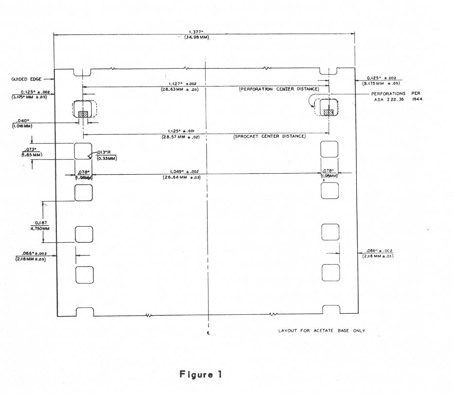
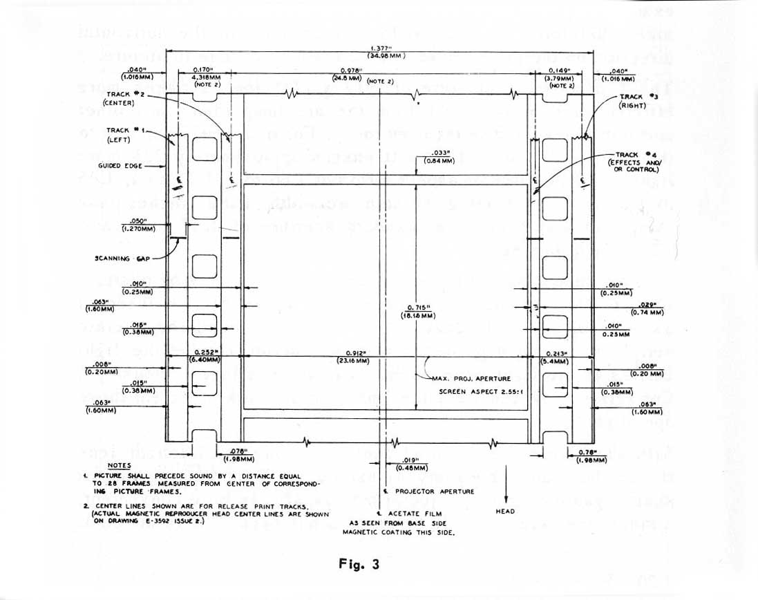
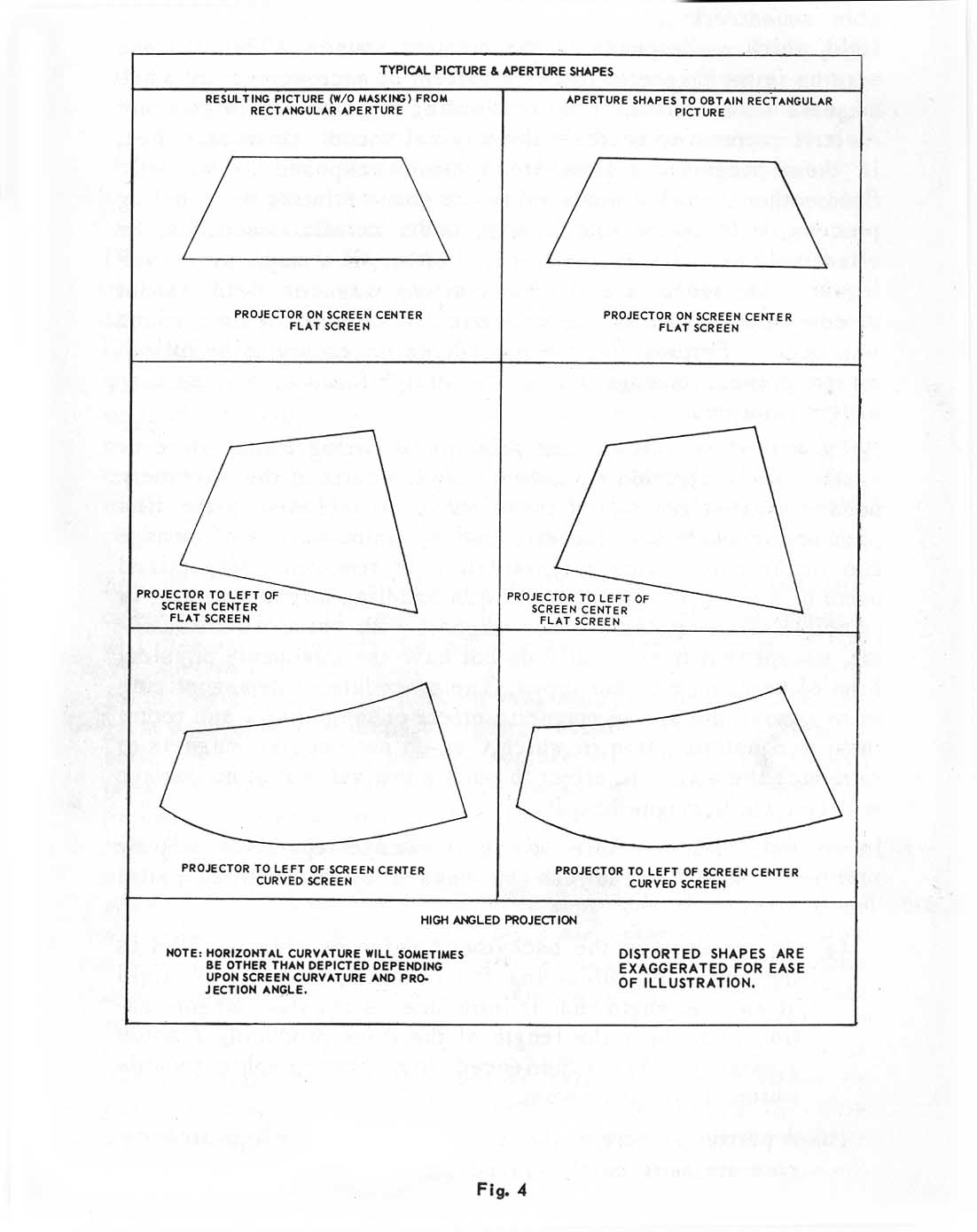
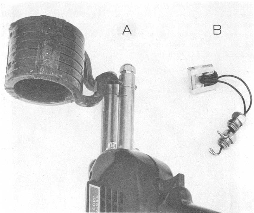
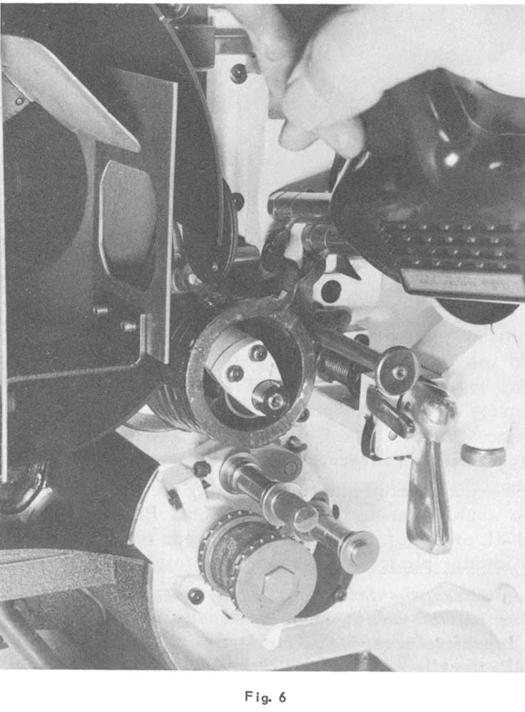
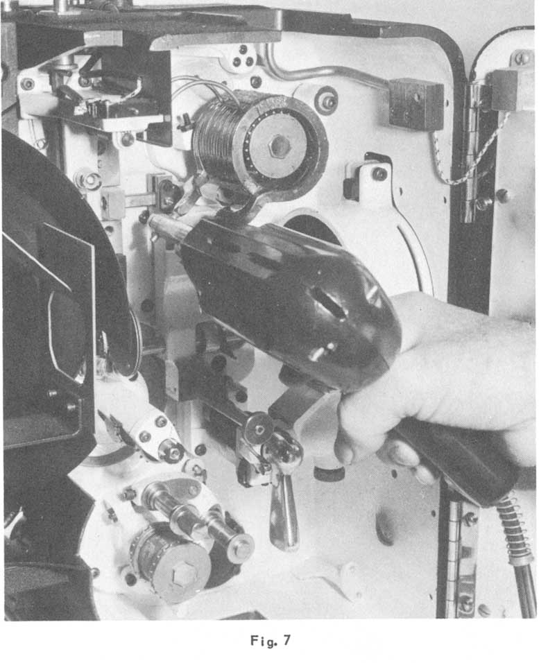
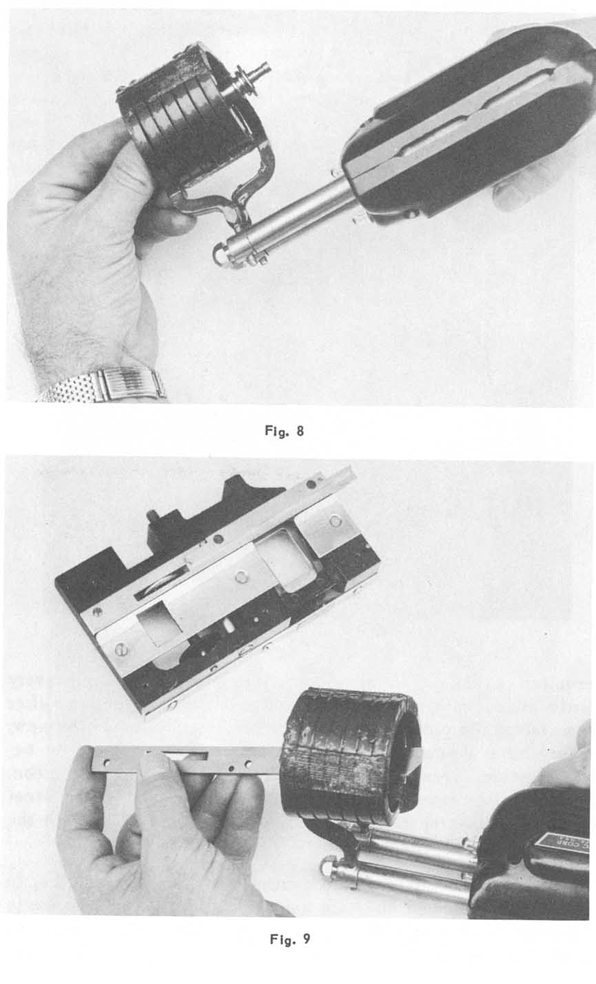
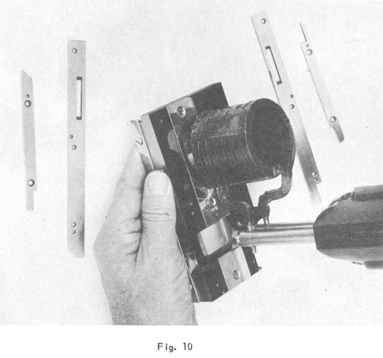
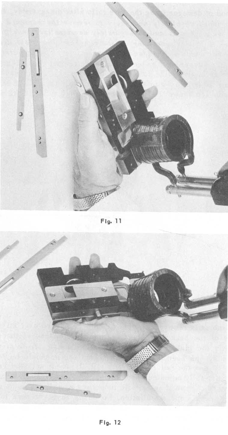
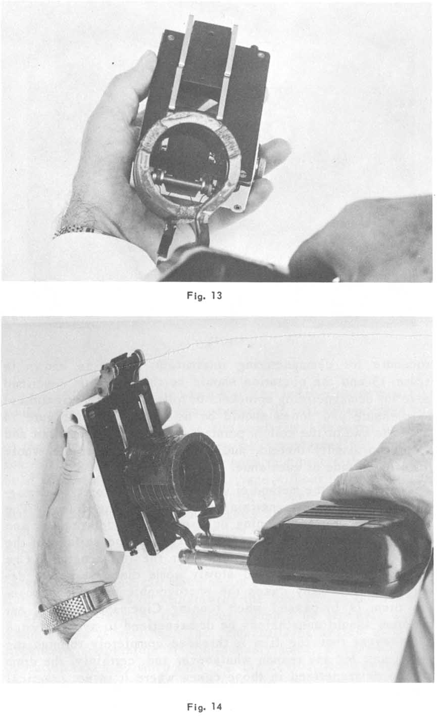
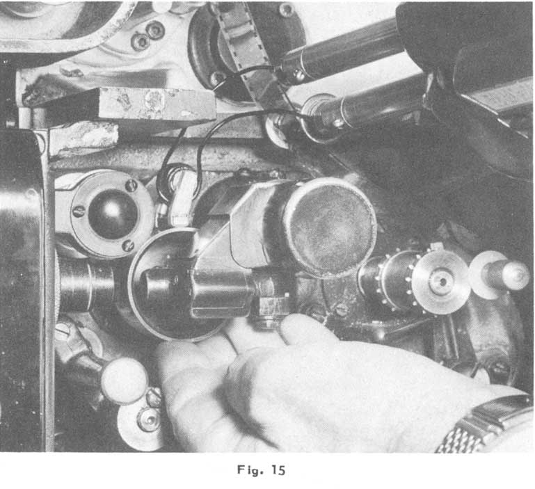
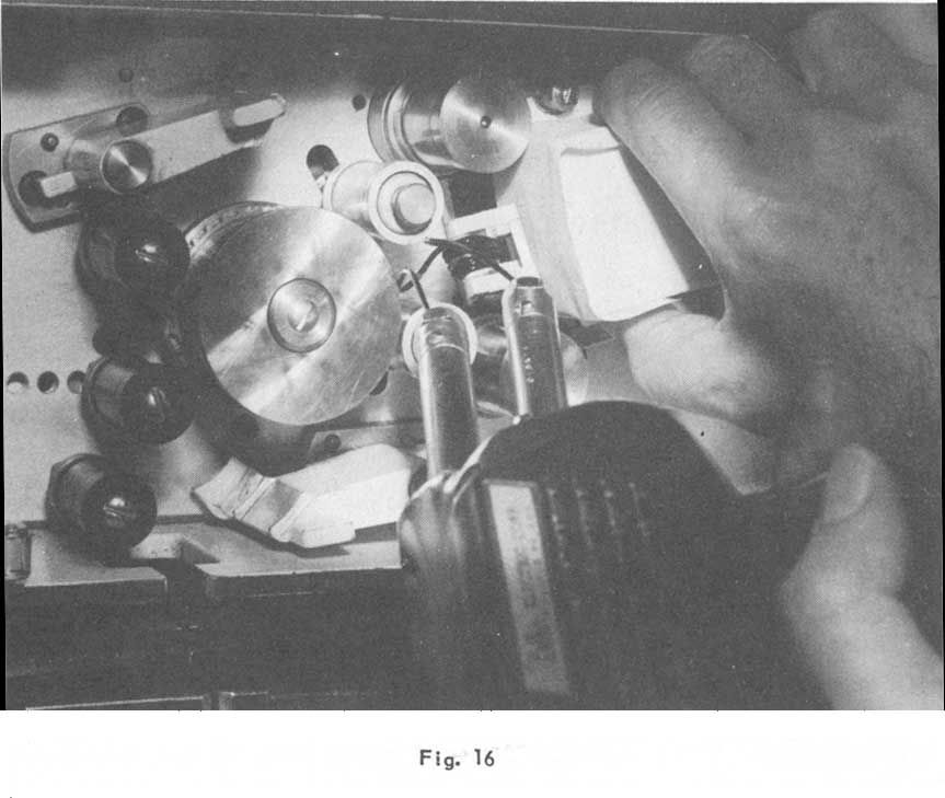
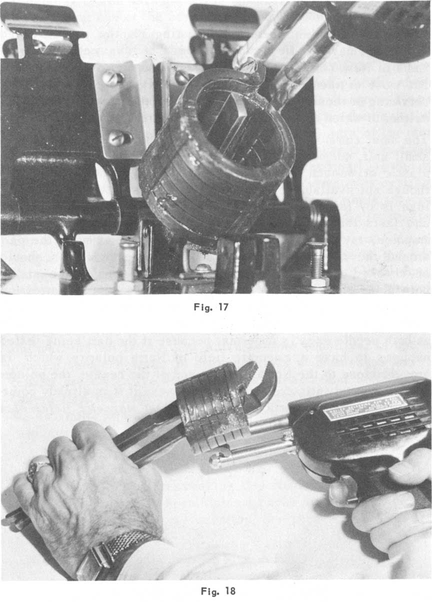
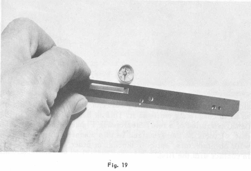
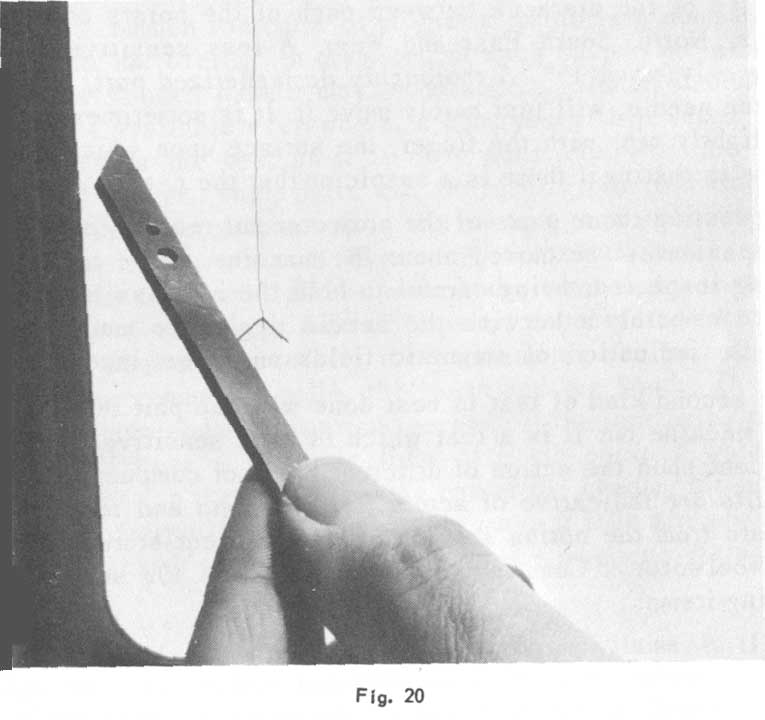
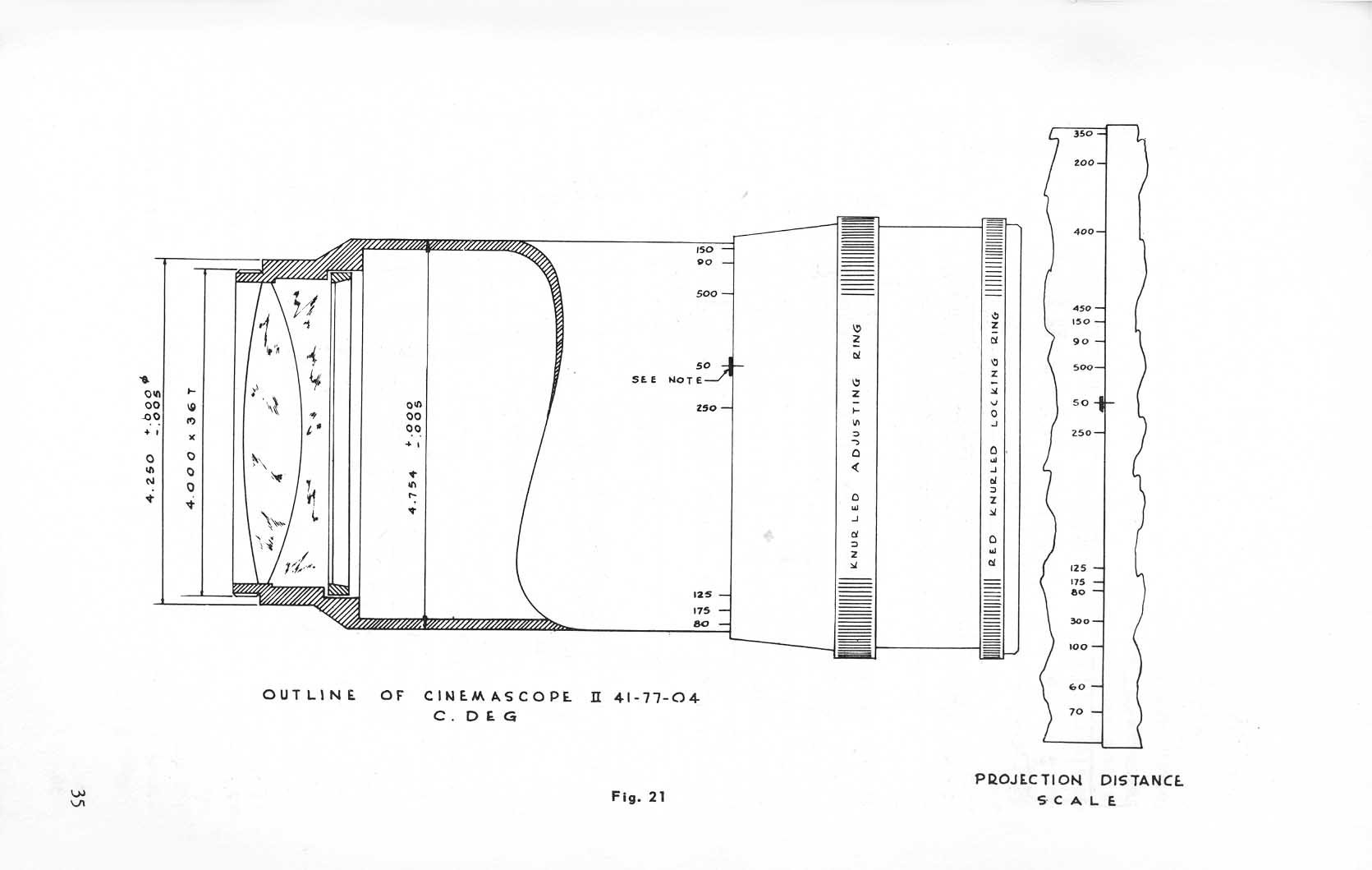
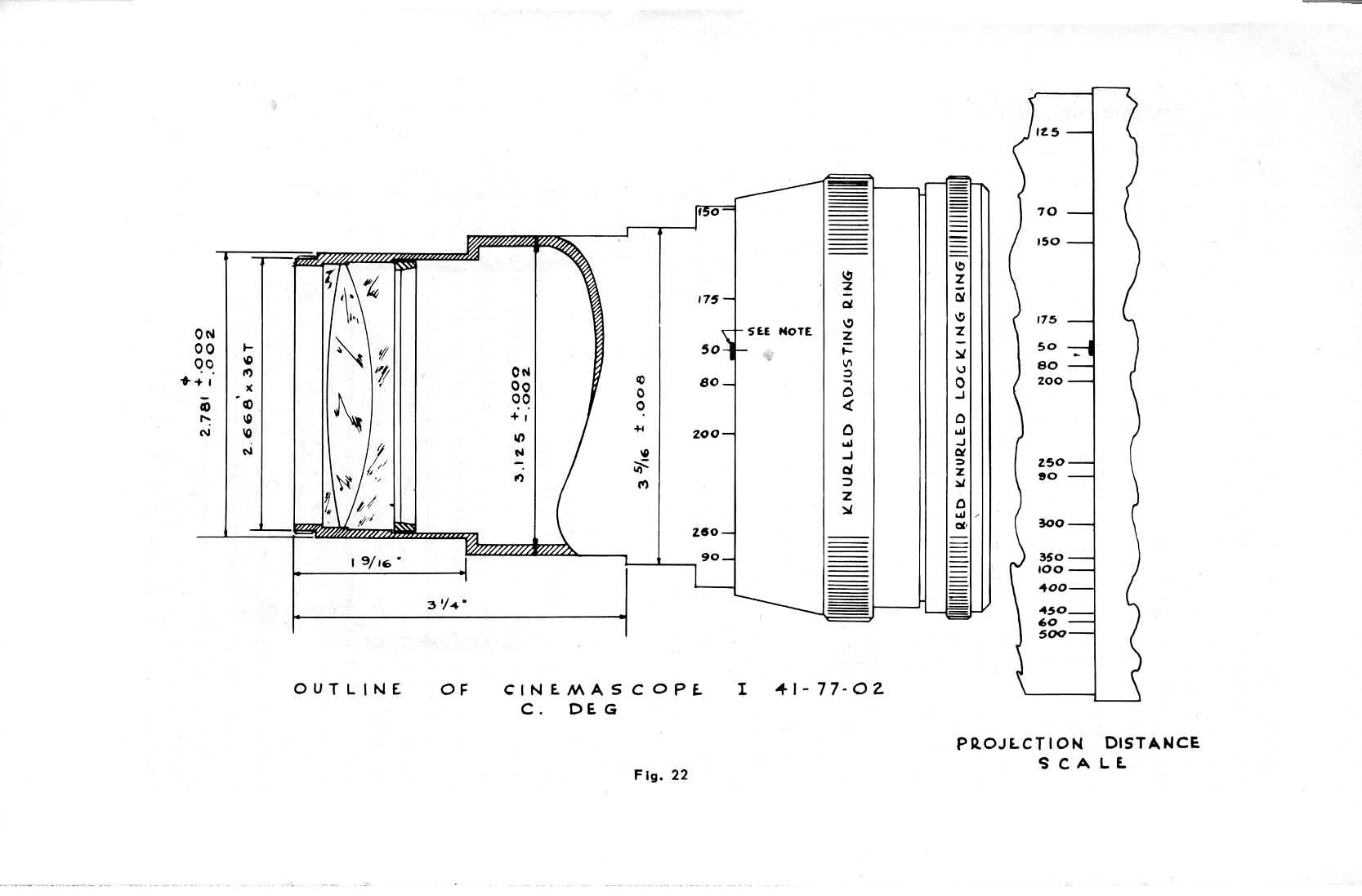
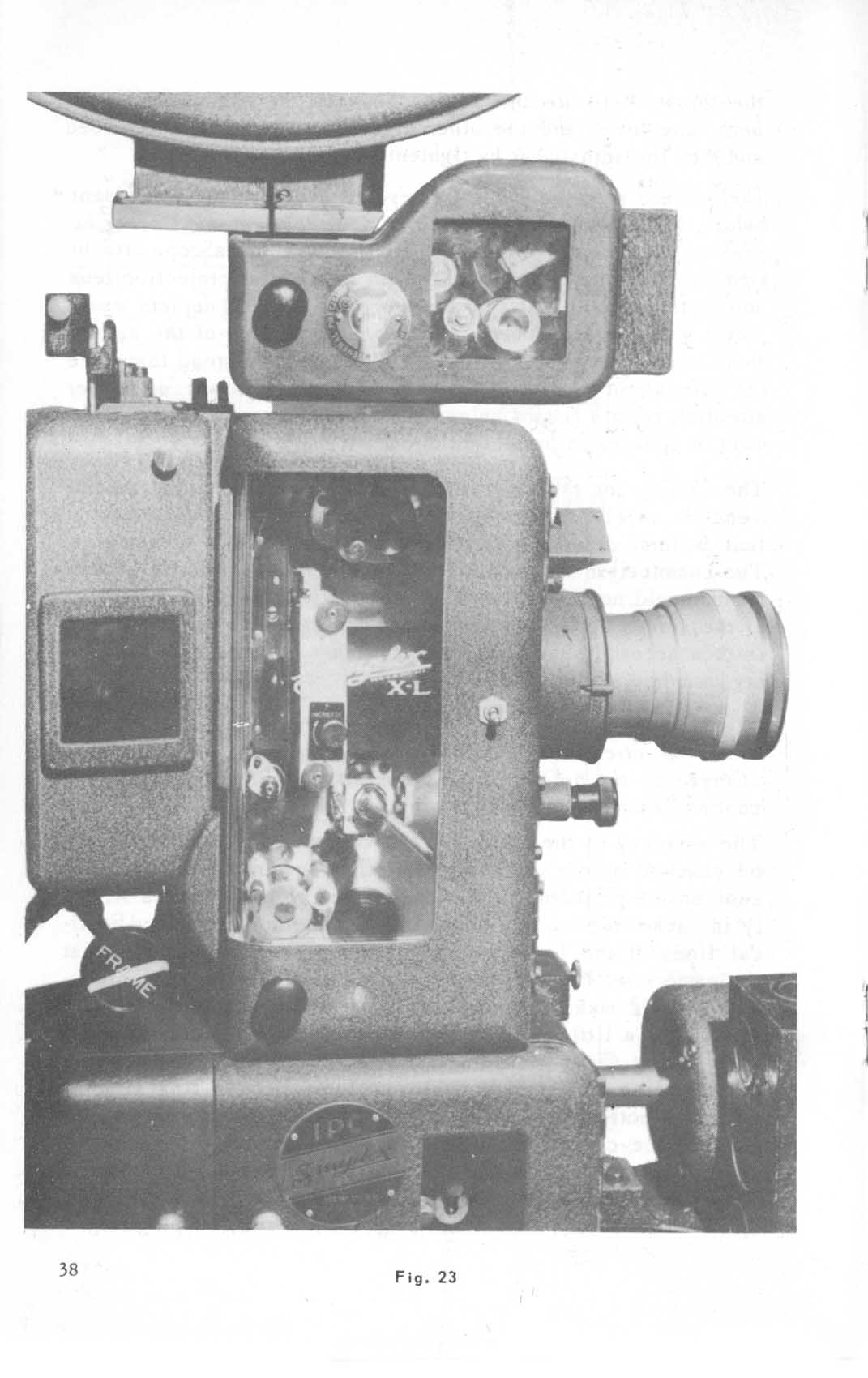

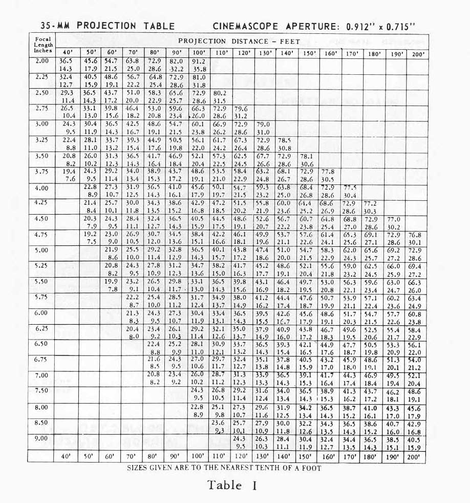
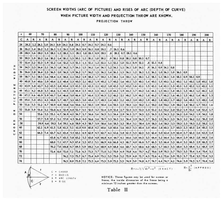
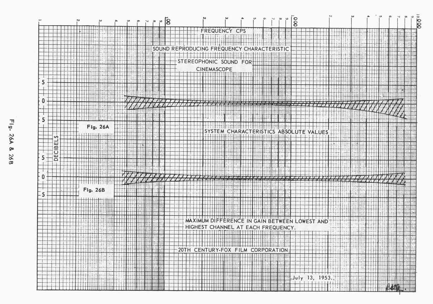
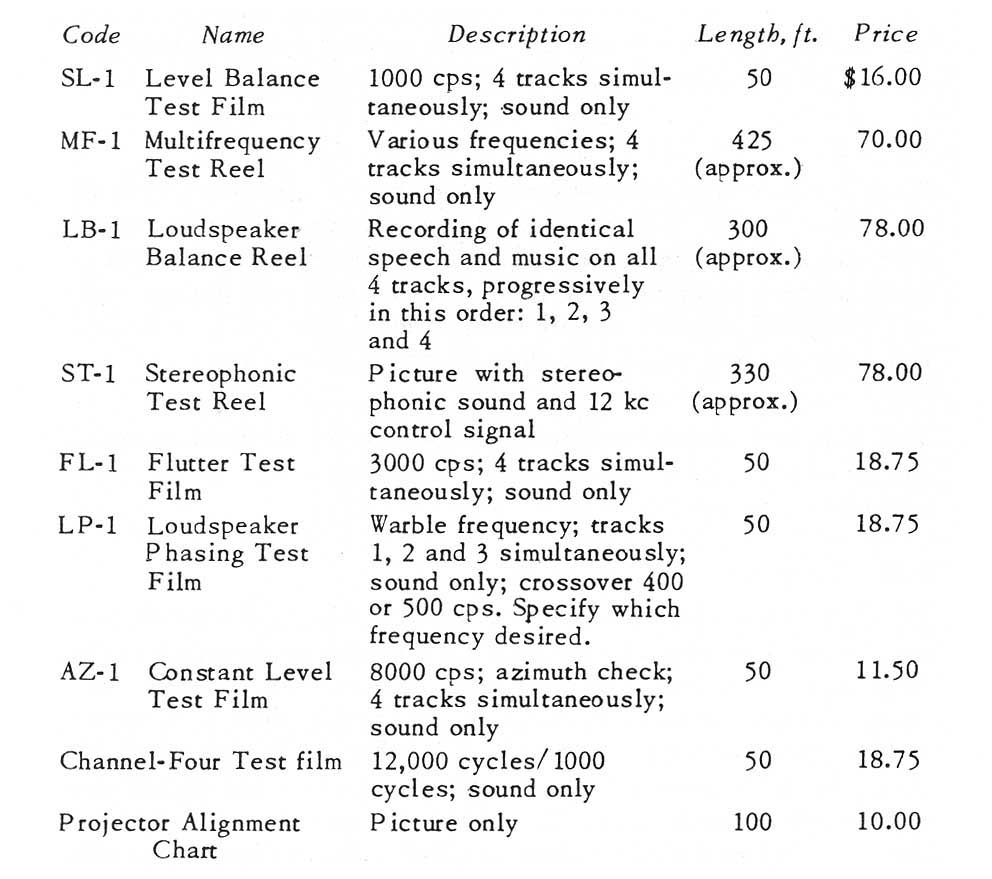
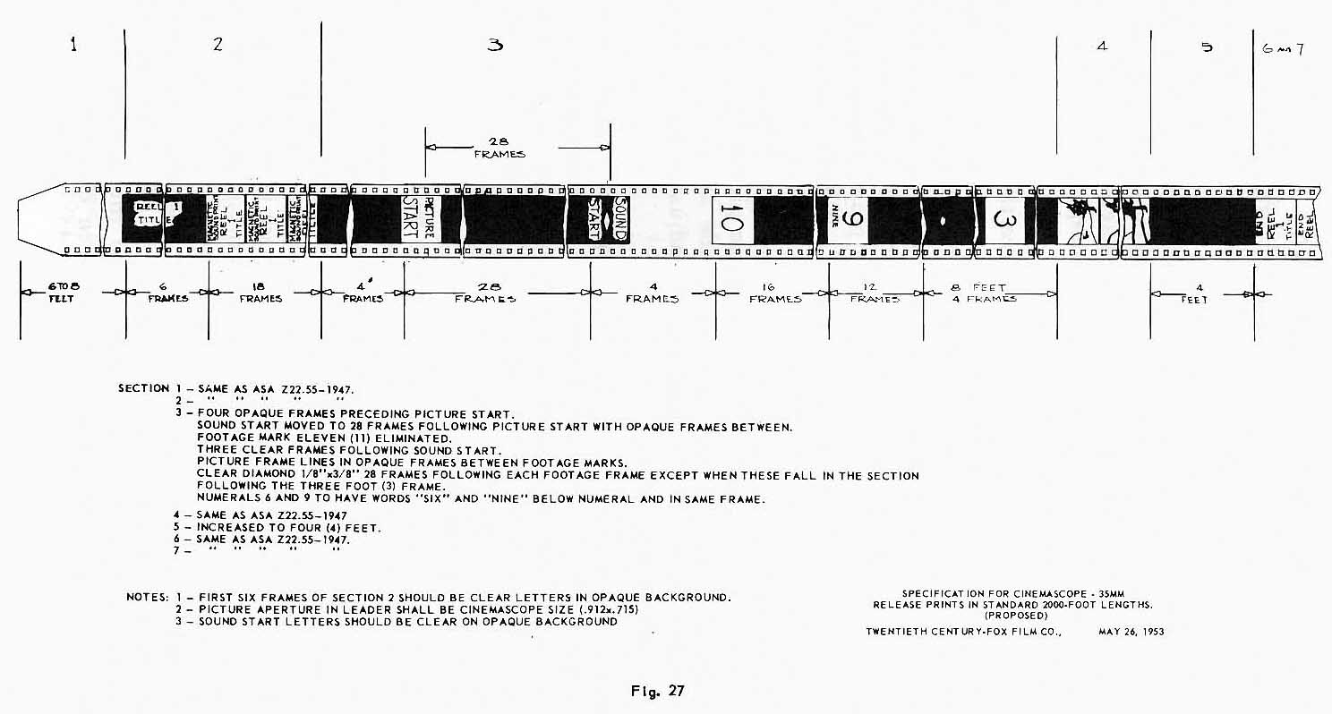
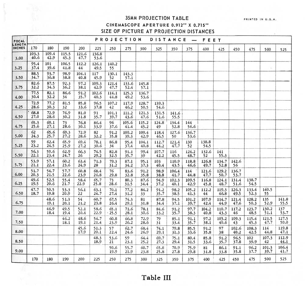
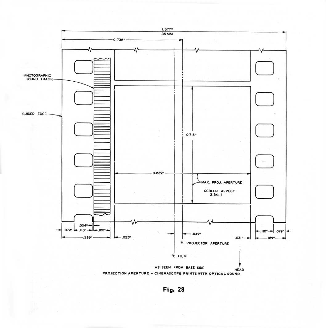
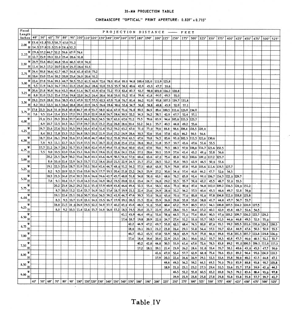
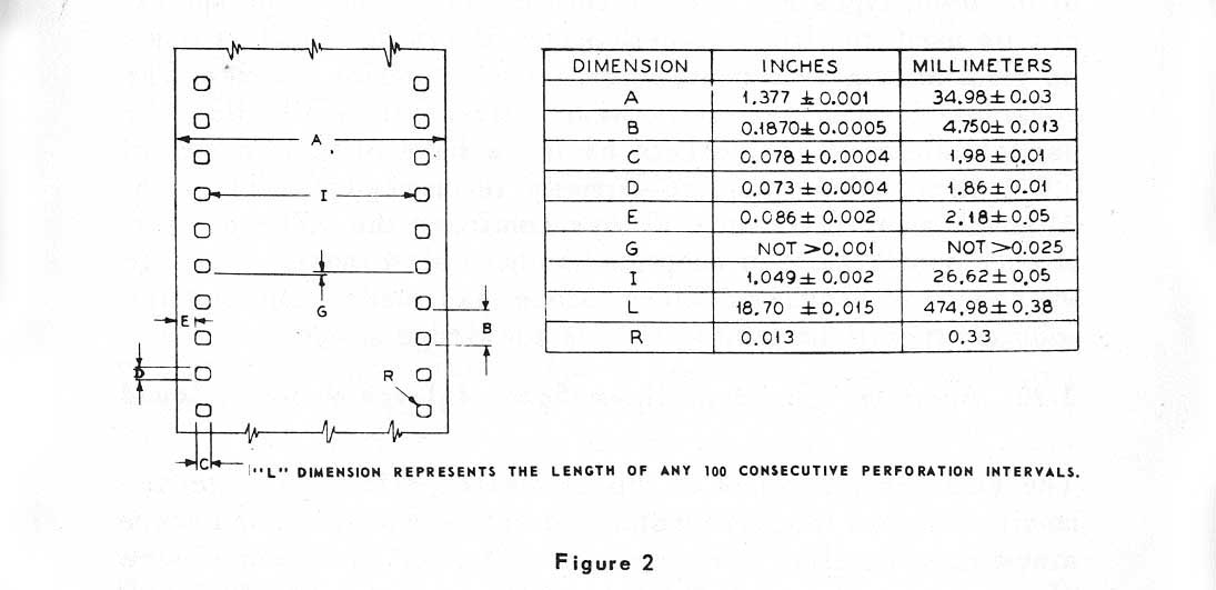