DUPLICATION OF COLOUR FILM USING COLOUR DUPLICATING FILM STOCKS
Contents:
|
|
|
|
Colour Intermediate Film for duplicating colour negatives
The Colour Intermediate system of duplicating colour negatives (first devised and published by Eastman Kodak in 1956) employs a multilayer colour film for preparation of both colour master positives and colour duplicate negatives. This procedure is much less time-consuming than the first method; also it eliminates the need for a registering-type printer. Proper removal of residual hypo and correct stabilisation treatment are essential to retard changes in the dye images to ensure long keeping and so, for long-term storage, black-and-white separations should still be made for protection purposes, but very rarely are.
Procedure
In this system, both the colour master positives and colour duplicate negatives are made on the current Eastman Colour Intermediate Film.
This is an incorporated-coupler type of multilayer film containing colour couplers similar to those used in Eastman Colour Negative Films. The upper, blue sensitive layer contains a colourless coupler, which is converted to yellow dye during development. A yellow filter layer prevents blue light from reaching the layers beneath. The next layer is green sensitive and contains a yellow coloured coupler, which forms a magenta dye during development. The residual yellow-coloured coupler becomes a mask to correct for the unwanted blue absorption of the magenta dye. The bottom emulsion layer is red sensitive and contains a pink coloured coupler, which is converted to a cyan dye during development. The residual pink coloured coupler forms a mask to correct for the unwanted blue and green absorption of the cyan dye.
Eastman Colour Intermediate Film also contains absorbing dyes, which prevent scattered light from travelling significant distances in the emulsion layers. By this means image sharpness is enhanced. These absorbing dyes are water-soluble and are removed from the film during processing. A removable black antihalation layer is coated on the back side of the support. When printed and processed as recommended the effective reproduction contrast of colour intermediate film is near unity so that the contrast obtained in the duplicate negative is similar to that of the original colour negative. This is an essential feature of the film as it is designed to be used in both stages of the duplicating system.
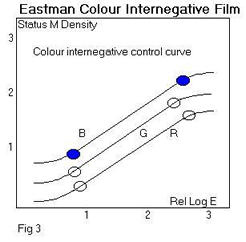
Status M or Certified MM filters are used for the densitometry of Eastman Colour Intermediate Film. The contrast of the film, as measured on a densitometer may not be exactly 1.0 as the density values obtained will not be true printing densities due to differences between the film spectral sensitivity and the combination of filter transmission and spectral sensitivity of the photocell. Typical "Best Fit Contrast" values for colour intermediate film would be Blue 1.02 Green 1.04 Red 0.93. The printing contrasts of the dye images are about equal for both specular and diffuse illumination, permitting either optical or contact printing to be done from the same duplicate negative.
Process Control
Control of processing Eastman Colour Intermediate Film is critical and it is necessary to adjust the development time and if necessary increase the developer agitation level, until the contrast levels are satisfactory. With low developer agitation a high blue contrast or low red contrast mismatch is likely.
Exposure of Eastman Colour Intermediate Film
To ensure that Eastman Colour Negative Film has optimum printing contrasts when making the first, positive, intermediate stage, and to retain optimum printing contrasts when printing the second, negative stage, energy at both ends of the visible-light spectrum of the printer light is removed. The Kodak Wratten Filter No. 2E, which absorbs light of short visible wavelengths, in combination with an efficient heat-absorbing glass such as the Chance ON21 or Pittsburgh 2043 (4mm thick) is optimum for this purpose and these two filters should be used in all printers and scene testers when printing onto Eastman Colour Intermediate Film from dye images.
Method - Preparation of the Master Positive or Interpositive
Step 1Monitor and adjust the process for Eastman Colour Intermediate Film to be certain that it conforms to the manufacturers' specifications. This is very important since any photographic variation from standard in the colour master positive stage will be multiplied in the colour duplicate negative stage.
Step 2 Prepare a printer test or test loop containing an original colour negative control strip, and a few selected frames from the work.
Step 3 Measure the Status M densities to blue, green and red light for the negative control strip. Also measure if possible the highest and lowest integral densities in the picture area of the selected frames.
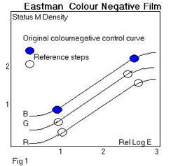
Step 4 Plot the characteristic curves for the negative control strip and designate the steps whose densities correspond with the highest and lowest densities of the picture area. These will be the reference points throughout the duplication procedure and represent the picture density range, which must be reproduced. (Refer to Figure 1).
Step 5 Print the test loop onto Colour Intermediate Film.
Step 6 Process the printed test loop footage in a standard process.
Step 8 Measure all of the integral densities to blue, green and red light of the control strip and the corresponding densities of the reference steps of the printed strip.
Step 9 On the characteristic curves for the control strip locate the positions where the densities of the reference steps of the printed scale occur on these curves.
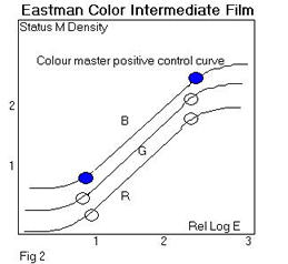
Step 10 If the picture density range does not fall on the linear portion of the sensitometric control curve, the printer exposure must be adjusted. If exposure adjustments needed for all three curves, removal or addition of neutral densities from the filter pack or adjustment of the printer light settings is called for. If exposure adjustments are needed for the individual blue, green and red curves, the filter pack must be modified by removal or additional of yellow, magenta or cyan filters respectively, or the printer light values altered.
Step 11 When the optimum printing level has been established print the original negative picture footage at these settings.
Preparation of Colour Duplicate Negative
Step 1Print the colour master positive (the correctly exposed print-through from part A step 11) onto the Colour Intermediate Film. A step printer of either the contact or optical type should be used at this stage.
Step 2 Process the print-through in a standard process for Colour Intermediate Film.
Step 4 Measure the integral densities to blue, green and red light the reference steps of the printed scale.
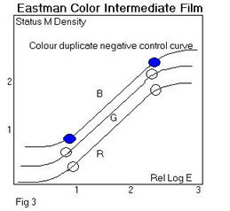
Step 5 Plot the characteristic curve for Intermediate and locate the positions where the densities of the reference steps of the print-through plot on these curves
Step 6 If the picture density range does not plot on the linear portion of the control curve, the printer exposure should be adjusted [see above].
Step 7 When the optimum printing level has been established; print the master positive picture footage and grey scale onto Colour Intermediate Film.
COLOUR INTERNEGATIVE FILMS FOR DUPLICATING COLOUR POSITIVES
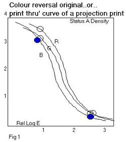
This system involves the preparation of a colour internegative on a multilayer colour film from a reversal colour original [or from any print]. The method [from about 1952] was introduced by Kodak for the production of large numbers of release prints, where a reversal printing system would be considered too expensive, or in places reversal print processing facilities were not available, or where a reduction or blow-up print was required. The positive material for which Eastman Colour Internegative Film was originally designed was Ektachrome Commercial, a rather low contrast camera film with a contrast of about 1.0 that was never projected. . Today this film is no longer made and the aim contrast of the internegative film has been reduced a little, but it is still too high. The original material had a contrast of 0.6 and it is still about 0.5. The ideal today would be 0.4.
Eastman Colour Internegative Film has become the workhorse material of the archive, as it is the only film whose contrast is in any way designed to produce of a negative from a positive projection colour print. It has a fixed contrast but there are some methods for reducing the contrast, in particular flashing, though none that are satisfactory, for increasing the contrast.
In using any of these systems, the basic rule for making master positives (either black-and-white or colour), colour duplicate negatives and colour internegatives is the same as that applied to normal black-and-white duplicating work - namely, to use only the straight line portion of the characteristic curves of the duplicating films involved. This procedure ensures that optimum tome reproduction will be obtained; in other words, a one-to-one transfer of the tonal values of the original will be effected.
Already in 1896 films were coloured by hand, frame-by-frame, using a very fine brush, and the technique probably originated from the hand colouring of lanternslides. The results obtained with this technique could be extraordinarily good, for example some of the works by George Melies.
The dyes used were translucent inks, paints or dyes in a water, or sometimes spirit base, and were applied by a brush or stippled on with a stippling brush onto the emulsion side. The gelatine of the emulsion absorbs water-based dyes easily. Opaque dyes were unsuccessful, as they would appear neutral or black on projection. Probably the dyes used most were those used for stencilling and were the same aniline dyes used for lanternslides, but there is almost no literature on the subject.
The technique was limited to the capacity of the colouring artist and was never developed industrially. Furthermore it was very difficult to apply the colour to a regular area of the frame without smearing and each frame has a slightly different amount of dye, covering a different area. In order to recognise this technique and separate a hand brushed film from a stencilled one, it is necessary to look at the variations from frame to frame, and in particular the difference in the spreading of the colour, the different amount of colour spread in an area, the lack of clean definition on the edges. This is often best seen as a fluttering of the coloured areas on the projected image.
It is quite common to be uncertain as to whether a film has been coloured by hand brushing or by stencilling if the hand brushing is well done, the stencilling haphazard or the dye rather pale or faded.
By 1906 Charles Pathe, owner of Pathe Frere and a great innovator in the cinematographic industry, already employed 200 workers in his colouring studio in Paris. The method used was that of a manual stencilling developed by Melies and Gaumont: for each colour to be painted on the film a positive copy of the same film is stencil cut by hand and then the emulsion is washed away. For each colour, there is, therefore, a corresponding transparent outline, or stencil, similar to the stencils used for silk screen printing, with the part cut away where that colour should be.
In manual stencilling the worker holds the stencil in the left hand exactly superimposed on the film while, with his right hand, dips the paintbrush into the colour (usually a basic aniline dye, but dyes of all sorts were used), partially dries it on a pad and places it on the stencil. A light stroke is used to transfer the colour through the cutout and onto the emulsion side of the film image.
The result was very precise (provided the stencil had been cut well), but the colouring process was extremely slow. Thus, when Pathe mechanised his production and expanded into markets throughout the world, he had to make some compromises in order to accelerate the process (the Pathe company coloured from 300 to 400 copies of each film by 1910). By 1908 a first version of the mechanical stencilling system was in use. The machine for cutting the stencils was extremely precise, based on a pantograph that enlarged the frame on a piece of opaque glass. The outline of the image that was to be cut out was traced on the glass by the operator using a pointer, which guided the device [not unlike a sewing machine with an oscillating needle], which cut the stencil. The resulting stencils, one for each colour, was a length of film of the same length as the final print. The emulsion was then washed off. The machine for colouring the positive copies used a sprocket wheel, which allowed a stencil and the positive copy to be pulled along together in contact. A velvet ribbon loop, continuously replenished with colouring agent from a tank, acted as the brush, transferring the dye through the stencil to the print. The procedure had to be repeated for each colour.
With the mechanised stencil colouring system as described in the patent literature of the time, it was possible to stencil a film with up to seven different colours at a time, in a single pass through the machine. Several investigators believe that even more than seven stencils were sometimes used. Other companies used the process, with minor differences, as well, such as Gaumont in France and Ambrosio and Cines in Italy. The system was used less after 1915, though it lasted until the end of the 1920s (Pathe's colouring studio was closed in 1928) and it seems that the continuous stencilling machinery was considerably more complex than the film processing machinery at that time.
The Pathechrome process, the trade name given to prints made using mechanised stencilling, used dyes applied on top of the black and white silver image, just like early hand colouring, and some of these dyes were the same as those used for dye tinting [see below]. A list of 9 colours was recorded in the Pathe literature. .
These same nine colours seem to have been in use from early in the century to 1929. The actual dyes used may not have remained the same, however.
Stencilling seems not to have been common in the USA. The Handscheigl Process of 1916 in US was used to colour some 15 or 20 movies and this produces prints with similar appearance.
The process used conventional lithographic printing to create separate printing plates to make up to three colours for printing onto a conventional black and white print. The areas to be coloured were defined by hand for every frame! De Mille's "Joan the Woman" was the first film to use this process, called then the De Mille Process. Eric von Stroheim's "Greed" also used it as well as printing onto yellow tinted film for some sections. The process was also called the Wyckoff Process.
Two methods are possible for the production of internegatives.
1.A generalised procedure can be established at the internegative production stage so that all internegatives are produced at a single printer setting and grading is carried out at the final printing stage.
2.The original positive can be graded by various means so that a "graded internegative" can be produced. The final printing stage is then a one printer light, and therefore a high-speed operation.
The second method will produce the best results, but with this duplication route various "hybrid" versions of the procedures can be used to produce overall quality more or less between the two alternatives.
Ideally a sensitometric control strip of the same film material as the original print film is used to print tests. This is obviously impossible if the original is an old coloured nitrate film or an extinct early colour print. After much testing it has been found that this is not all that critical and a control strip of a modern colour print film works reasonably well.
Procedure 1 - Grading at final printing stage only.
Step 1Plot the curves for an Internegative control strip whose process is on aim (Status M) and make up the strip as a loop or length for printing
Step 2 Measure the highest and lowest integral densities to blue, green and red light for typical scenes of the picture footage to be duplicated. Provided a frequent check is carried out the reference steps can be considered permanent for a particular type of print original.
Step 3 Indicate on the control curve the step numbers whose densities most closely match the highest and lowest picture densities above - physically mark these steps on the control strip as they will act as reference steps for the duplication process.
Step 4 Print the colour print control strip onto Colour Internegative Film.
Step 5 Process the printed strip in a normal process for the film, usually ECP-2.
Step 6 Measure the integral densities to blue, green and red and the reference steps of the printed strip (Status M).
Step 7 Plot the characteristic curves for the control strip and mark the positions for the densities of the reference steps of the print-through
Step 8 The reference steps should plot on the linear portion of the control curves. If they do not, an adjustment in the exposure must be made. Colour adjustments can be made by using filters of adjusting additive printer light settings or trim settings.
Production
Step 9 When the exposure levels have been adjusted, the picture footage is printed onto the Internegative.
Step 10 Print the internegative on Colour Print Film using normal grading methods.
|
|
|
|
Procedure 2-Grading at initial printing stage only.
Step 1Monitor and adjust an ECP-2 process until on aim for Internegative.
Step 2 Print a standard Eastman Colour Internegative strip on an automatic additive printer with the trim controls and main controls set centrally (if B & H Trim: 12, 12, 12, Main: 25, 25, 25).
Step 3 Process
Step 4 Plot a full Internegative curves and mark off the print-through densities of the highest and lowest patch densities of the standard Internegative original for all these colours.
Step 5 Assess the R, G, B shifts required to fit the standard original range onto the centre of the straight-line portion of the Internegative curves.
Step 6 Adjust the trim controls of the printer to achieve this and record these values.
Step 7 Repeat Steps 2-4 until correct positioning on Internegative curves are achieved.
Setting up the printer
Step 8 Produce the best possible print from Internegative on Colour Print Film on any printer (High Speed Additive preferred) an analyser can be used for this.
Step 9 Record which printer, RGB Trim and main controls are used for this, and the batch of print film.
Setting up the Video Colour Analyser
Step 10 Produce best possible print from original standard Internegative on Colour Print Film This should print at 25 25 25.
Step 11 Set analyser to show a matching print on reversal setting with main controls at 25, 25, 25 by adjusting analyser trim controls.
(This is the normal setting up procedure for an analyser).
Production
Step 12 Analyse originals on analyser as if they were to be printed on a reversal print stock (insert standard Internegative as check - should analyse at 25, 25, 25) and produce punch tape.
Step 13 Print production originals onto Internegative using duplication printer with trim settings as defined in Step 6 and grading data produced in Step 12.
Step 14 Print production internegatives on final stage printer with trim and main controls as recorded in Step 9.
Note
Some graders pre-grade the originals visually, and use these values to produce the printer light settings in Step 12.
Another system (introduced first in 1968) used to exist and made use of a colour reversal duplicating film called Eastman Reversal Intermediate Film 5249. Use of such a film meant that, for making a duplicate negative, one printing/processing stage was eliminated. Reduced graininess and improved sharpness did not compensate for a very difficult material to process reliably and repeatably, and in 1993 it was discontinued. It was never extensively used for archival restoration work, however many archives will possess duplicate negatives made on this material.
Existing CRI material can be printed normally. It is thought that this film will fade considerably and the techniques for its restoration will be similar to restoration of a faded negative.
LABORATORY AIM DENSITY [L.A.D.]
Eastman Kodak established this simplified motion picture duplication control in the 1970's because it was felt that most laboratories did not actually use the 2-point systems shown above! As a result the quality was extremely variable resulting in smoky shadows, blocked-in highlights, contrast mismatches and poor colour reproduction. For duplication control, many commercial laboratories used a standard scene negative made by themselves, or sometimes a "china girl", made by a manufacturer or technical society, a density patch on a piece of negative, or just guesswork. Rarely did two laboratories use the same control system or work to the same aims. Inconsistency was, and still is, one of the biggest problems.
The 1959 Gale and Kisner 2-point methods and the derivative methods based on them that are described above are undoubtedly the best method of control and are strongly recommended for critical work on archive film. Their system of duplication recommended test printings of a control strip. The print-through is used to peg the shadow and highlight densities. This 2-point [also sometimes called full curve] method is still valid but many laboratories find it too time-consuming to use as a routine duplication control method so a simplified system to reduce variability and improve quality was designed and this is known as the L.A.D. or Laboratory Aim Density method. John A Pytlak and Alfred W Fleischer, SMPTE Journal, Vol 85, Oct 1976 published it in full in the paper “A simplified motion picture laboratory control method for improved colour duplication”.
The LAD Control Film provides both objective and subjective control of a duplicating procedure.
Description
The Kodak LAD Control Film is made on intermediate film, which is exposed from an original negative in a way that it prints exactly like an original camera negative. A description of the image will be found in Ch 8. There are specification densities for the large grey patch in the LAD Control Film which if followed throughout each printing or duplication stage will produce good tone and colour reproduction since achieving the aim density ensures that the range of densities falls on the optimum positions on the characteristic curves and these densities are listed in the Table of aim values.
2.Proper tone reproduction can be quickly determined by visually viewing the image of the girl's head at any stage of duplication. Loss of shadow detail would be indicated by no difference between the 2.5% black patch and the adjacent unlit plush black background behind the model. Loss of highlight information would be indicated by no difference between the white patch and the "white reference" frame line. And, of course, all six steps of the grey scale should be visible with proper tone reproduction, i.e. graduation to grey from white to black, with little or no colour shift.
Current Laboratory Aim Density values
On the Kodak Standard negative the LAD Standard Patch Status M densities are:
R - 0.80
G - 1.20
B - 1.60
The characteristic curve of 5247 shows that these densities are chosen to be exactly mid scale between highlights and shadows.
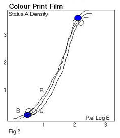
When printed correctly on Eastman Colour Print Film 5384 the LAD Standard Patch will measure on Status A:
R - 1.10
G - 1.06
B - 1.03
[This is a neutral grey of 1.00 visual density on the print (1.00 END) for a xenon arc projection light source.]
A Master positive on Eastman Colour Intermediate Film 5243/7243 will measure [Status M]
R - 1.10
G - 1.50
B - 1.90
A Duplicate negative will measure Eastman Colour Intermediate Film 5243/7243 will measure [Status M]
R - 0.90
G - 1.30
B - 1.70
Master Positive on Eastman EXR Colour Intermediate Film Colour Intermediate Film 5244/7244 will measure [Status M]
R - 0.90
G - 1.30
B - 1.70
Duplicate Negative on Eastman EXR Colour Intermediate Film 5244/7244 will measure Eastman Colour Intermediate Film [Status M]
R - 0.90
G - 1.30
B - 1.70
An internegative on Eastman Colour Internegative 5272/7272 will measure [Status M] R - 0.90
G - 1.30
B - 1.70
Using lad for black and white duplication
Black and white duplication follows exactly the same principles but requires the control of only one density value.
Original B/W negative [Status V] D - 0.65
B/W Fine Grain Positive [Status V] D - 0.75
B/W Fine Grain negative [Status V] D - 0.75
Eastman colour reversal intermediate film
LAD data for Eastman Colour Reversal Intermediate Film 5249/7249 is useful reference for checking existing archive duplicates. The stock was used to produce duplicate colour negatives in a single printing operation. The film was a reversal stock with an integral mask and a contrast of 1.0. It was discontinued in 1993, as the quality of the resulting duplicate was not as good as one made on conventional intermediate due to image streaking and process inconsistency.
If the LAD print has been left on the front of the duplicate negative it will be possible to measure the densities of the LAD patch to see if the duplicate has been correctly exposed. Using the standard printer light above, a correctly exposed CRI will have LAD patch print through densities of:
Blue 1.70
Green 1.30
Red 0.90
Note that these densities are each 0.10 higher than the 5247 patch.
This means the CRI LAD patch will print 4 Bell & Howell printer lights higher than the original 5247 patch. Therefore when checking full graded CRIs for colour/density on a colour analyser, a good guide is that a CRI should print at approx. 29 - 29 - 29 if the Laboratory standard printer light for LAD is 25 - 25 - 25.
Other useful lad aim values for old stocks
'Ektachrome' Commercial 7252
R - 1.10
G - 1.10
B - 1.10
Colour Internegative 5271/7271
R - 0.90
G - 1.30
B - 1.70
Colour Positive Print 5281/7381 & 5383/7383
R - 1.09
G - 1.06
B - 1.03
Densitometer variations
There may be differences in responses among densitometers. Apply any densitometric difference between Kodak's responses and a particular densitometer, if known. However, these differences are usually negligible, especially for making intermediates.
Density Corrections and Gammas
Since the various film stocks have different gammas, or contrast, a change of one printer point will not always result in the same density change.
The approximate gammas of the more common colour films are:
Film Gamma
5291/7291 (used as an internegative) 0.60
5249/72491.00
5243/72431.00
7252 (used as a printing master) 1.20
5272/72720.50
5384/73842.00 (midscale, near LAD)
7389/73991.00
73901.40
7 Density Changes
Below is a chart showing the approximate density expected when various exposure adjustments are made:
Film Change in Density (Midscale)
Change in printer points+ 1+ 2+ 4+ 8
5291/7291+ 0.02+ 0.03+0.06+ 0.12
7252- 0.03- 0.06- 0.12- 0.24
5234/7243+ 0.02+ 0.05+ 0.10 + 0.20
7389- 0.02- 0.05- 0.10 - 0.20
7399- 0.02- 0.05- 0.10 - 0.20
5272/7272+ 0.01+ 0.02+ 0.05+ 0.10
7390- 0.04- 0.07- 0.14 - 0.28
5384/7384+ 0.05+ 0.10+ 0.20+ 0.50