Bell & Howell Model C
Bell & Howell Lamp House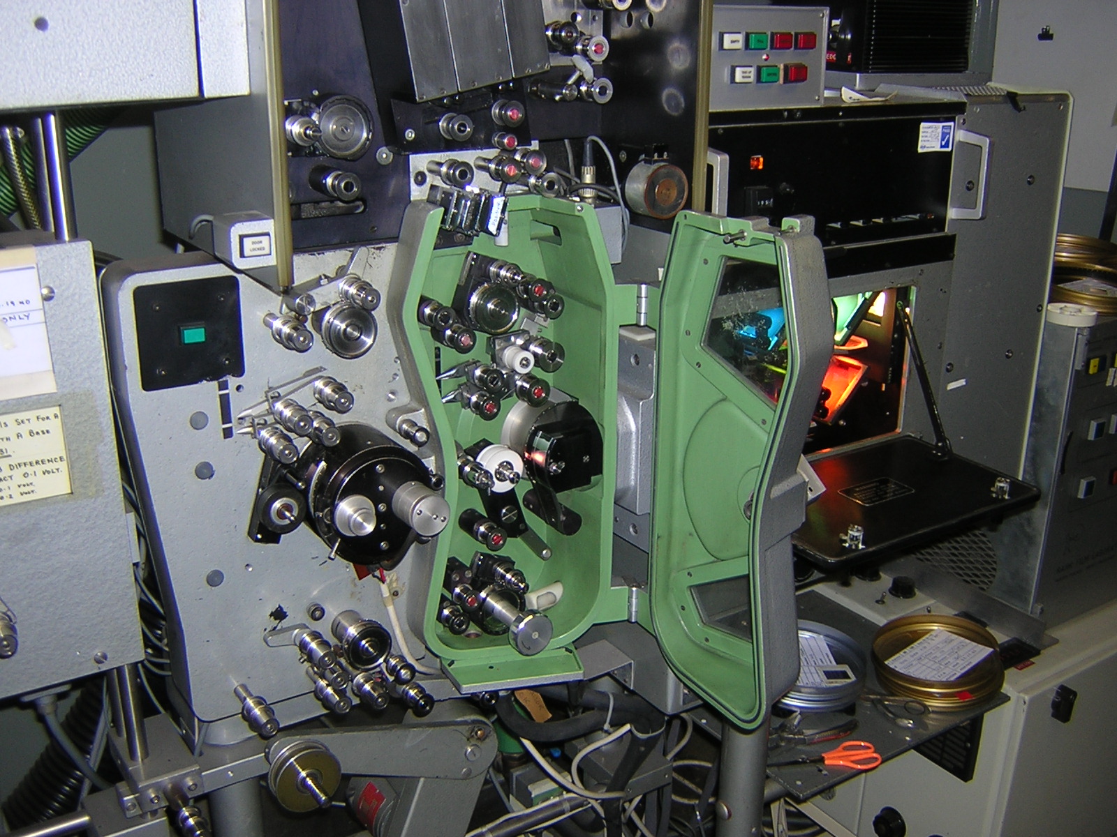
The Bell and Howell Additive Lamp house can be considered one of the major steps forward during the for colour printing. Prior to its introduction in 1961 colour correction was usually carried out by the use of colour filters. Debrie printers were used in Europe for colour printing because it was relatively easy to attach filters to the grading band used to control the light value. A metal clip was used to attach the filter. It was also possible to do the same thing using the system that used the photographically produced grading band.
Click thumbnails to enlarge the pictures.
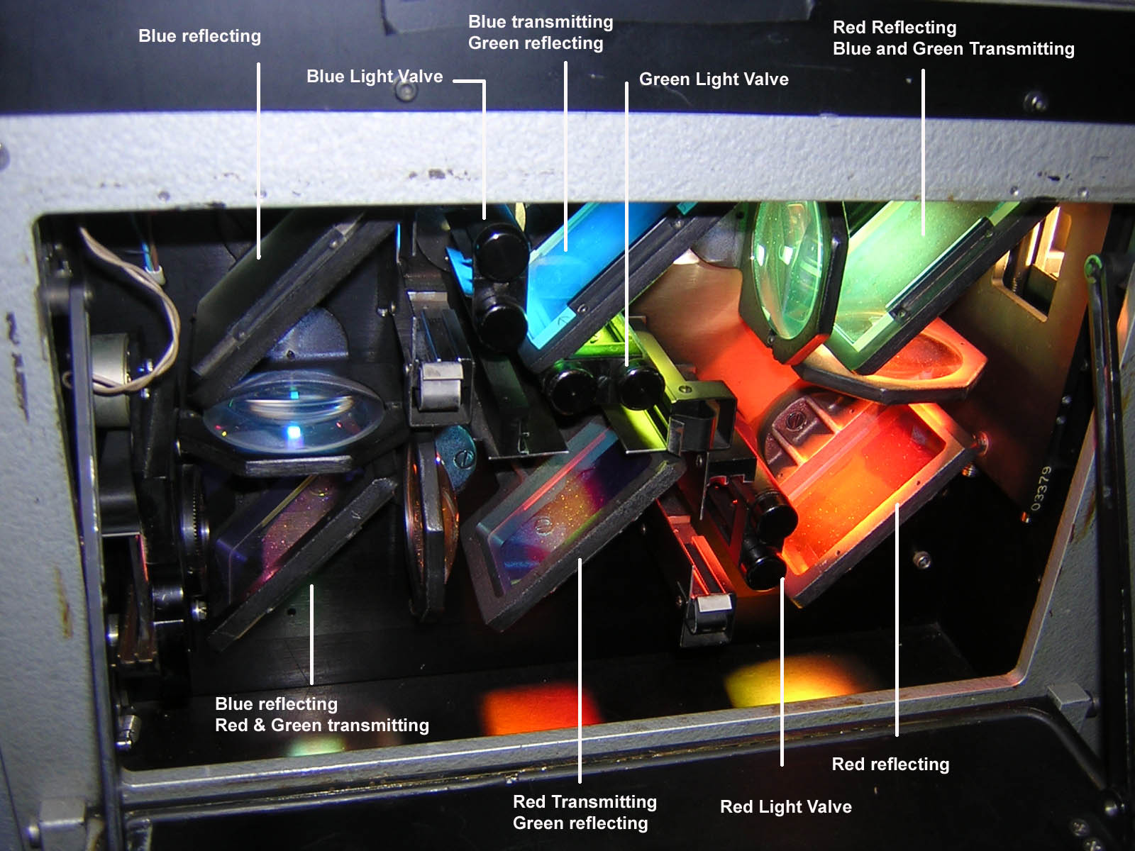
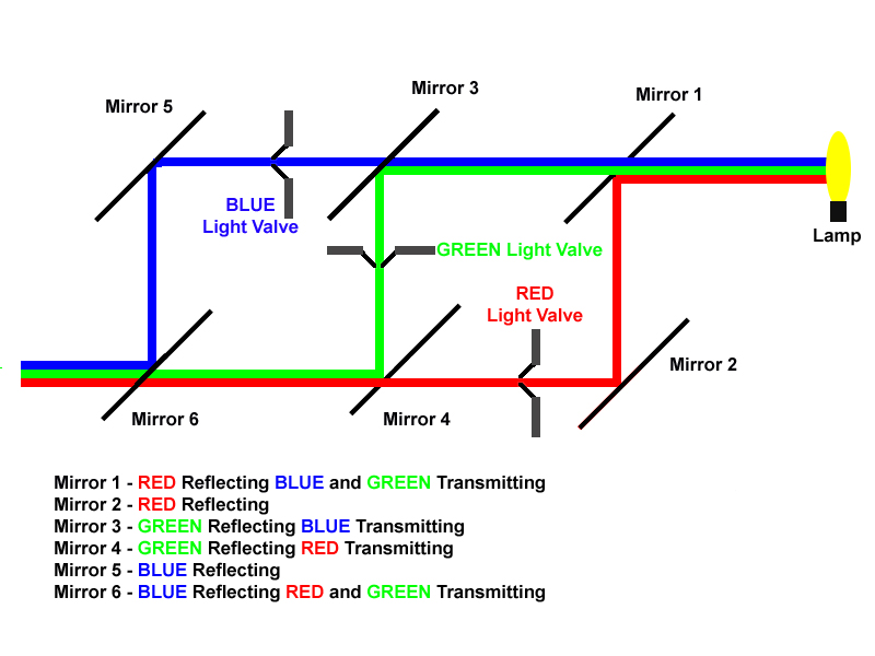
The two major components of the lamp house are the dichroic mirrors (Dichroic - having or showing two colours) and the light valves. The mirrors, six of them, divide the white light from the lamp into red, green and blue components. The light valves then control the amount of each colour which are then recombined to produce the printing light. The mirrors also remove unwanted parts of the spectrum. The pictures and diagrams above show the layout of the lamp house and the various components.
Bell & Howell Light Valve
The Bell and Howell Light valve was patented on 19 January 1966 by Willi G Engel and assigned to the Bell and Howell Co of Chicago, Illinois. The full patent can be read here US Patent 3454328 by kind permission of the Director of the European Patent Office. It has 50 light value steps which can be adjusted by a further 24 trim settings. The trim settings allow the range of the 50 lights to be moved up or down by 24 lights. These are mainly used to adjust the calibration for different film stocks. Each light step is 0.025 Log E exposure change, 12 printer points double or halve the amount of light i.e. going from light 12 to light 24 gives twice the amount of light and from 24 to 12 halves the light. Being an electro-mechanical device it requires a finite time to change light values; going from light 1 to light 50 requires about an 1/8 of a frame at 180 ft per minute.
In more recent times the electro-mechanical valve has been replaced by an electronic light valve which can be continuously adjusted and makes almost instantaneous changes; it is possible to make light changes on adjacent frames.