Light Valves.
Modern printers employ light valves. These were first introduced by Bell and Howell in 1965 on their Model C printer and from that time, all manufacturers have been using them on all rotary printers and many others. The light intensity is varied by moving vanes or rollers or diaphragms and most comprise some form of motor that rotates eccentric rollers through precise arcs to rapidly change the total light passed between them. The vanes or rollers are moved by mechanical linkage in mechanical light valves which are still very widely used but those supplied today are the newer electronic light valves that use electro-mechanical means to move them.
In modern additive lamp houses, the light valves are used to modulate the amount of light for each colour (Red, Green and Blue). In this diagram, you can see the principle upon which additive lamp houses work. The White light coming from lamp L is split into the three colours by dichroic mirrors. These are mirrors, which reflect certain wavelengths (= colours) and let other wavelengths pass by. By using them, the white light is divided into Red, Green and Blue. Each beam of coloured light is then focused by a condenser lens onto each light valve. The three light valves are operated separately, so that they can modulate the light by letting more or less - let's say - Red light pass by.
After this, the light is recomposed by use of other dichroic mirrors, and the resulting light is sent to the printing aperture through another pair of condenser lenses, which focus the light on the film.
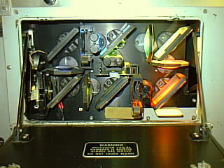
Here you can see an actual additive lamp house as mounted on a B&H Model C printer. You can recognise the mirrors and the light valves.
Mechanical light valves have preset positions for the vanes corresponding to each printer light value, whereas electronic light valves are continuously variable allowing each light valve to be identically matched. Mechanical light valves require the next light value to be stored electrically because they are relatively slow in operation, whereas electronic light valves are almost instantaneous in action and do not need the printer light value information stored prior to the change.
The shortest distance between light changes will depend on the speed of the printing machine and whether it is a mechanical or electrical light valve. The mechanical light valve requires six frames between changes, the electronic 2 frames, at 180 feet per minute (or 48 frames per second) on 35 mm.
The amount that the light changes from one value to the next is known as a printer point. The value of a printer point was at one time different between one manufacturer and another but today is standardised at 0.025 Log E so that grading data from one printer can be used on another. The printer points used today are sometimes called Bell & Howell printer points. The amount of light is doubled every 12 printer points increase [0.3 Log E]. and the range of points is from 1 to 50.
Light valves are fitted with controls called trimmers or trims, to allow light valves to be adjusted and calibrated. There are 24 positions on the trims each of which also alters the setting by 0.025 Log E. Neutral density filters can be placed in the light beam of a light valve to make gross adjustments of light and the trims are used to make fine changes to the light to adjust for the different speeds of stocks.
The B&H Model C uses a computer paper tape with eight rows of holes and a row of tractor feed holes. The first six holes have values of 1,2,4,8,16 and 20. The other two holes are used for start and stop information and information for automatic fades. Each light value is recorded as a set of three rows of holes because the Model C is designed for additive colour printing so the Red Green and Blue light information is required for each cue. When printing B/W each row has the same numbers. It is worth noting that although it is normal for the values to be R G B some labs use B G R.